Monthly Archives: July 2017

Building a Bartop Arcade Machine – Part 2

First I want to say thanks to all the people that have reached out just to tell me how nice my build is. I poured a lot of time into it, and I don’t do things halfway. Hopefully these post will pass on some knowledge to others. Always feel free to ask questions and I’ll help where I can.

Control Panel

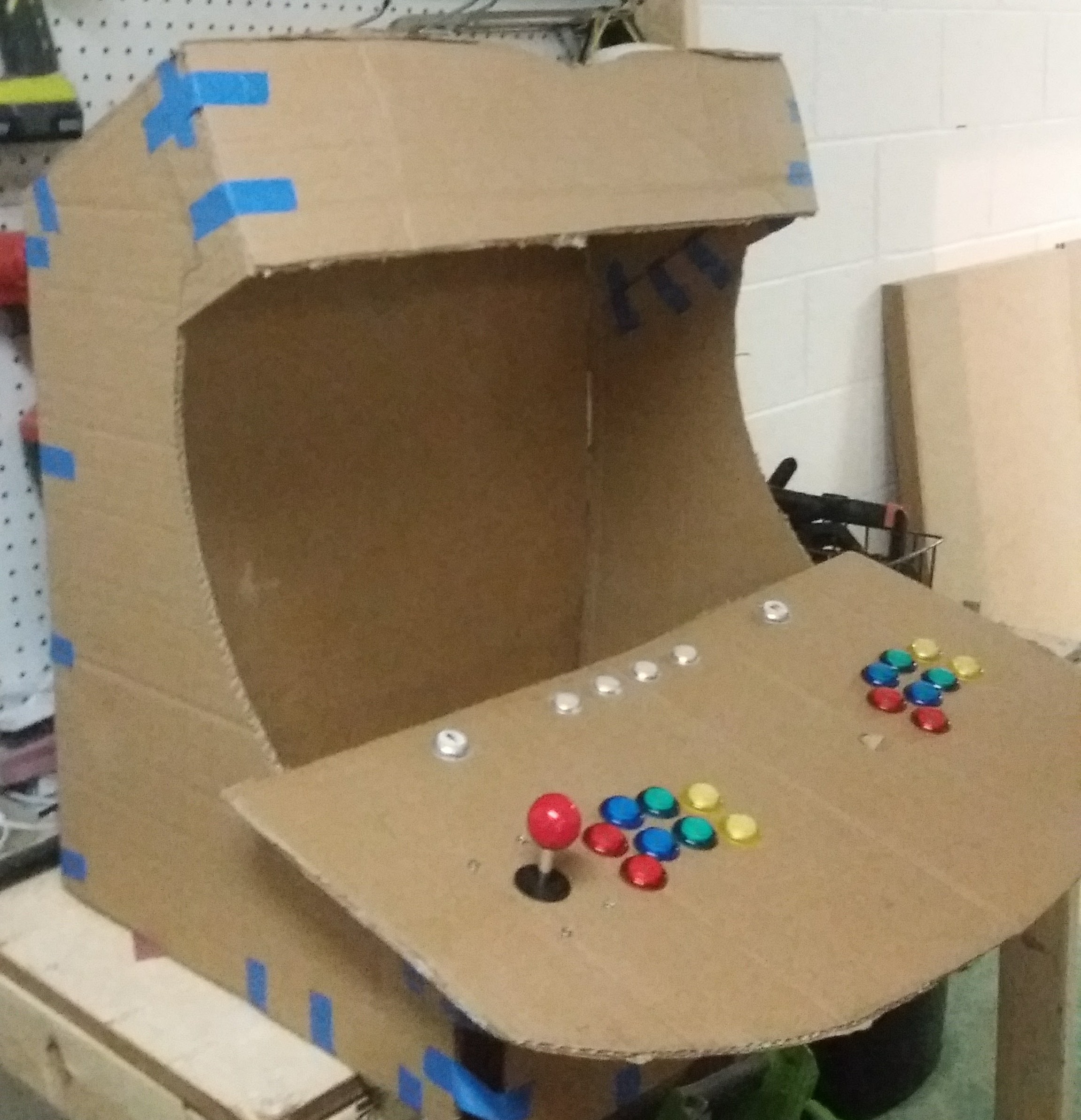
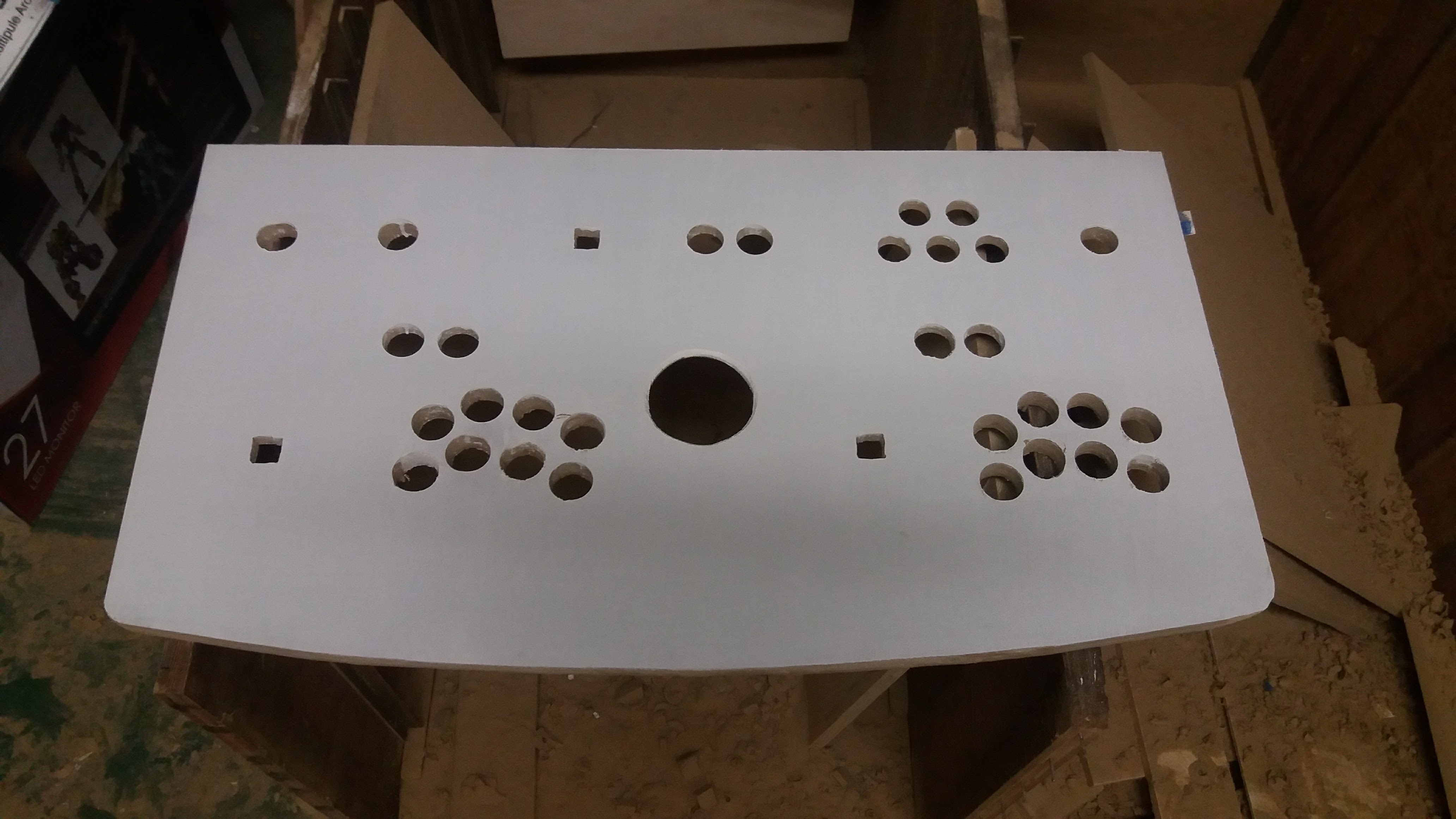
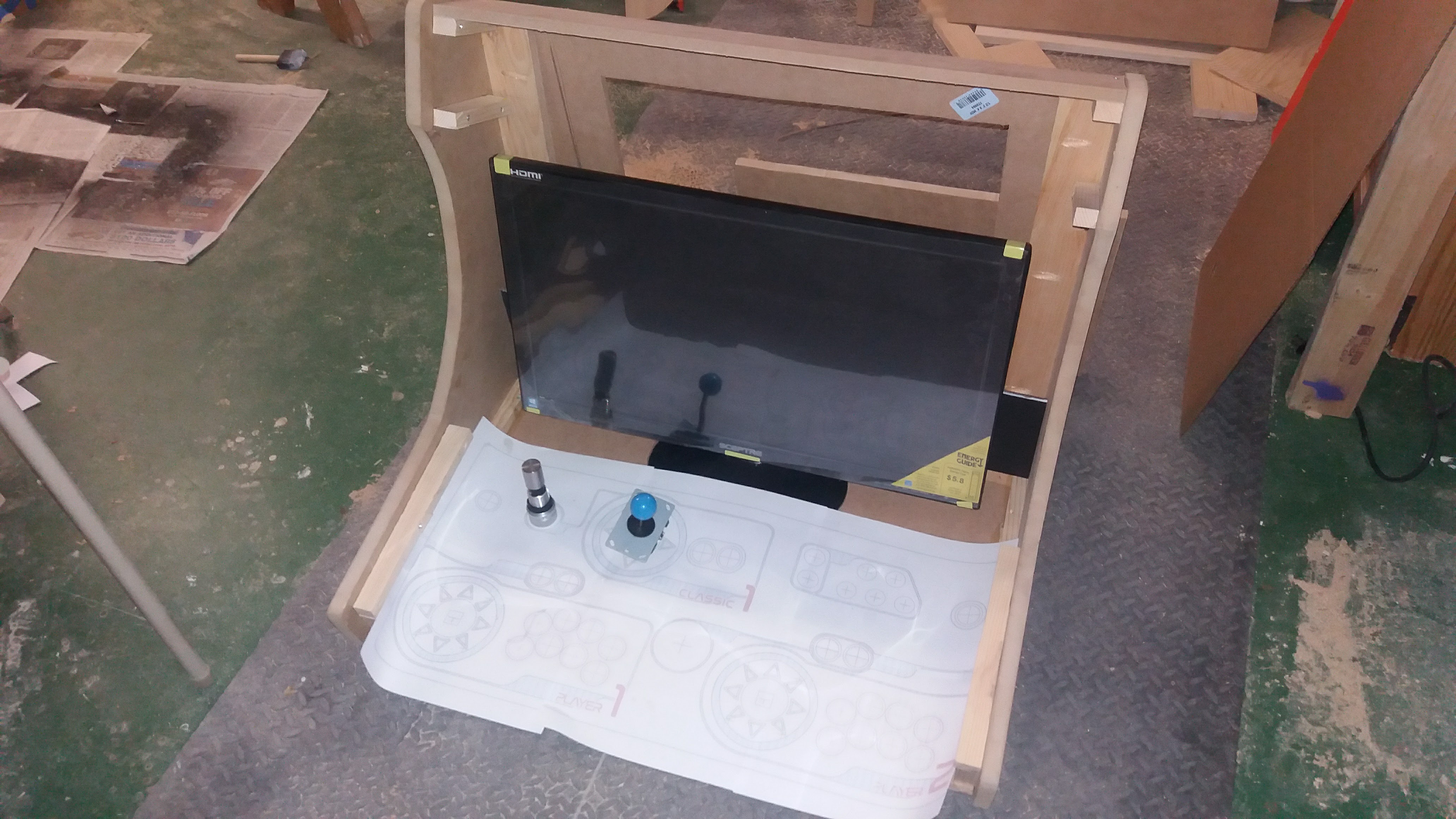
One person emailed me asking for a good starting place. I responded by saying to plan out your control panel first. My control panel changed three times and ultimately forced my to scale my monitor size up from 22″ to 27″. You can see the first iteration of the control panel that I made from cardboard here:

20170306_120601

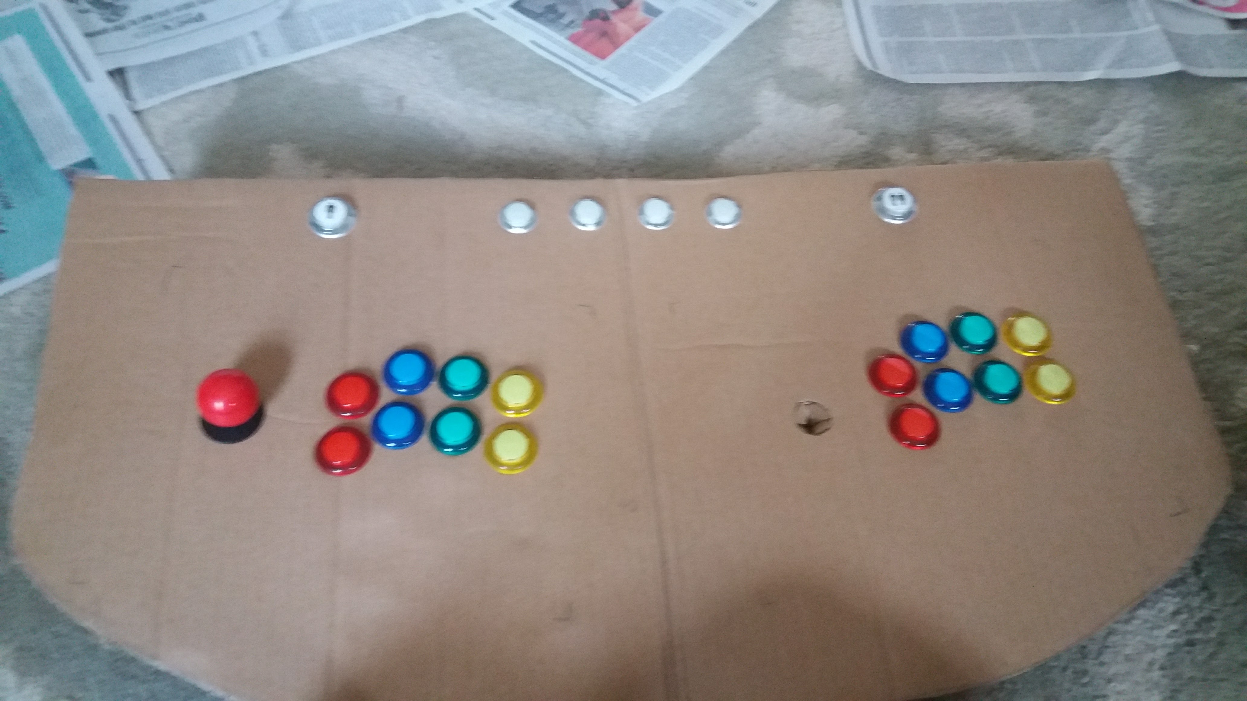
I would definitely construct everything in cardboard first just to get an idea of scale and measurements.

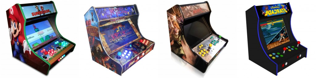
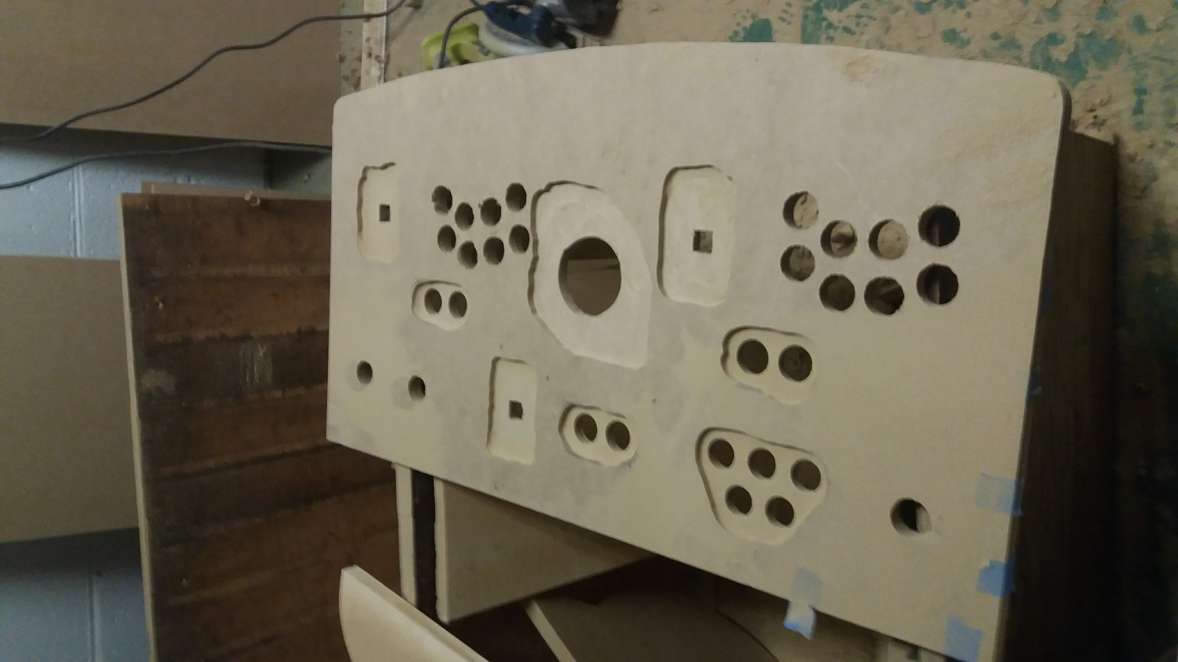
My ending design for the control panel wasn’t actually done in cardboard, but at that point I had done the control panel two times and figured that the final iteration was good enough to call “final”. After the design was finished, I sent it off to GameOnGrafix.com and got it printed up. I highly recommend them. They print amazing quality and they provide you with a cutting template.

20170405_130328 20170405_130306

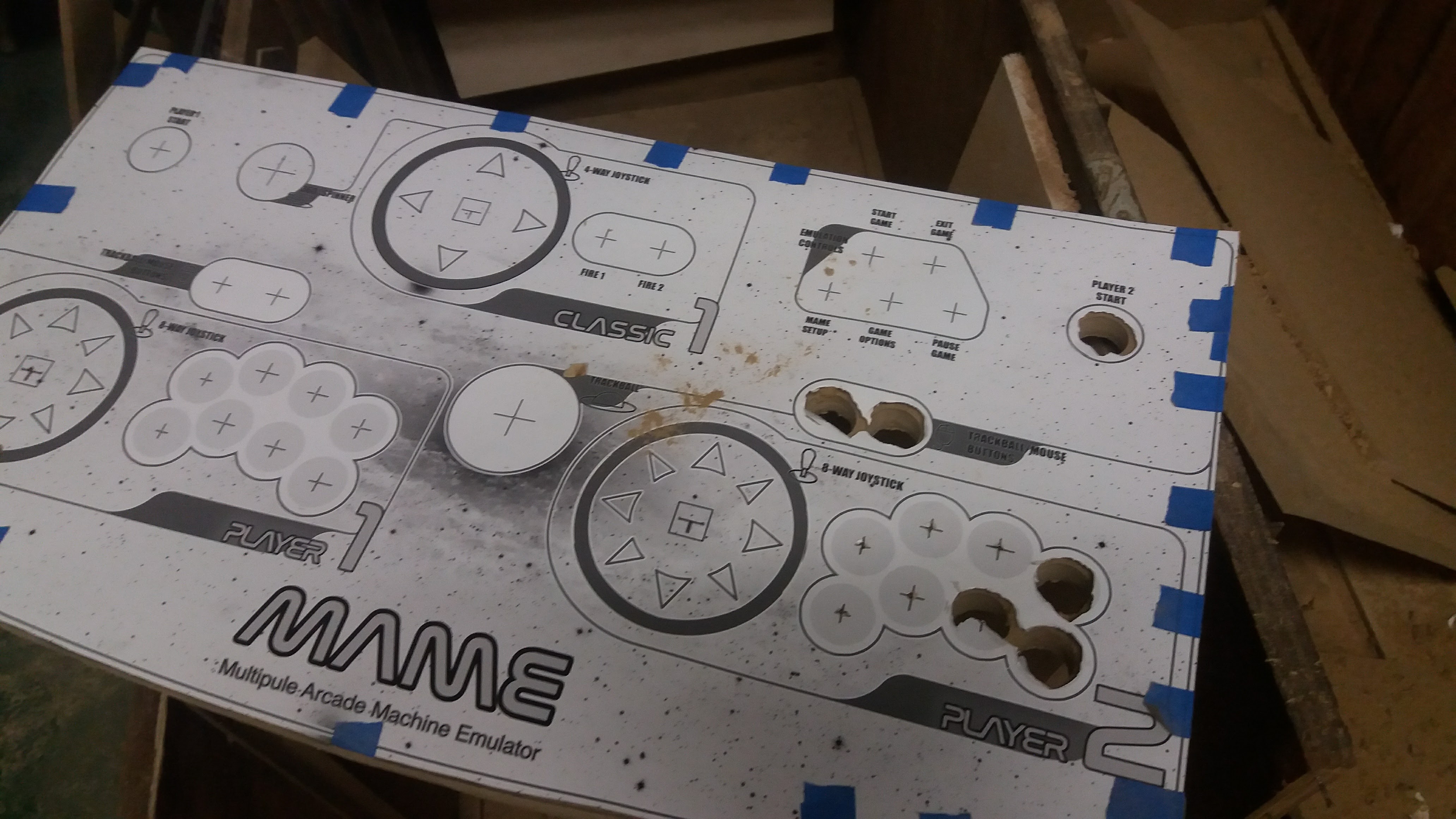
This is where you’ll need the spade drill bits that I mentioned on the tool list. The larger size is for the full size arcade buttons and the smaller size is for the control buttons that I placed near the player two button in the upper right corner. I used a jigsaw to cut out the square holes for the joysticks after using a drill to start the hole.

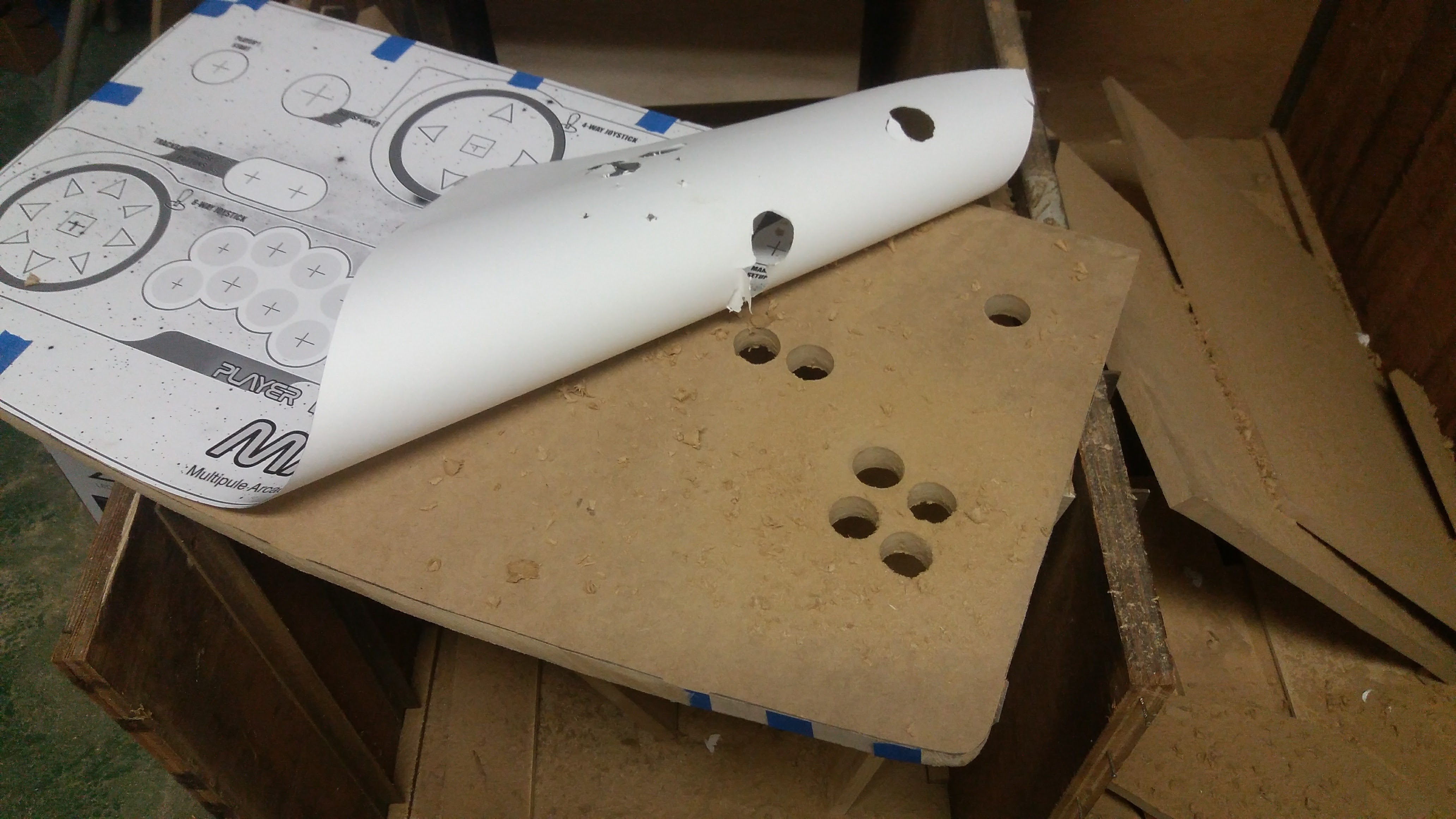
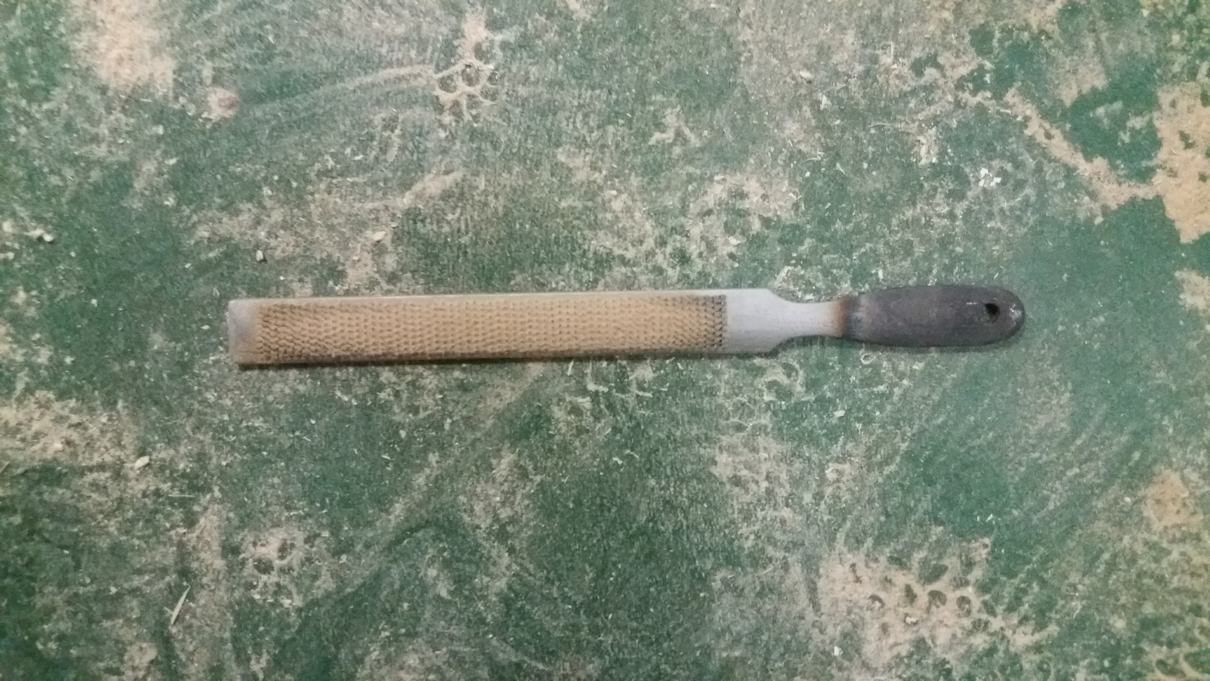
I also used the template to cut the curve on the bottom. But because I’m terrible with a jigsaw, I cut just a little away from the edge and used a file to get the shape just right. I’d highly recommend this technique.

20170313_115502

Here is the finished control panel board. I covered it will KIlZ Primer because the sticker adhesive for the control panel print out will not stick to MDF Board without it. This is very important. Nearly everything in the build is covered with KILZ first before I paint or stick anything to it. MDF board just doesn’t do well without being primed first.

20170422_182406

Next, I used a router to cut out the areas for buttons, the joysticks, and the trackball. Fortunately, the previous owners of our house left a ton of stuff and told us they didn’t want it. This included a very nice router. Lucky me! All you need to do is hold the casing for these up to the control panel bottom and trace them. You can see that all of my buttons didn’t need to be routed. Only the ones that weren’t tall enough to feed through the control panel. Again I’ll warn, please wear a mask and goggles or you will cough for days and your eyes will irritate you. It also works well to scare your kids. 🙂

20170422_14102820170422_134748

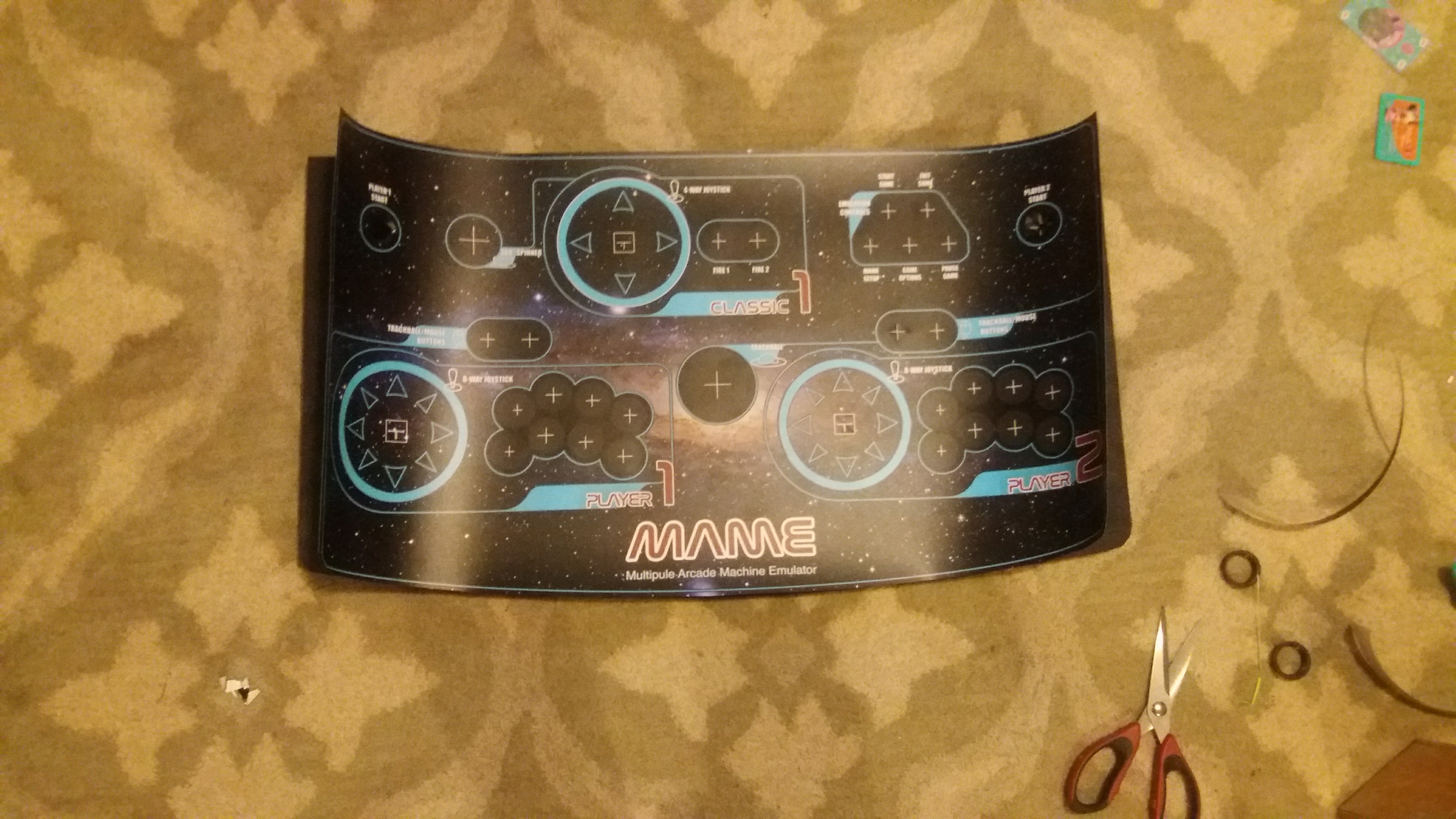
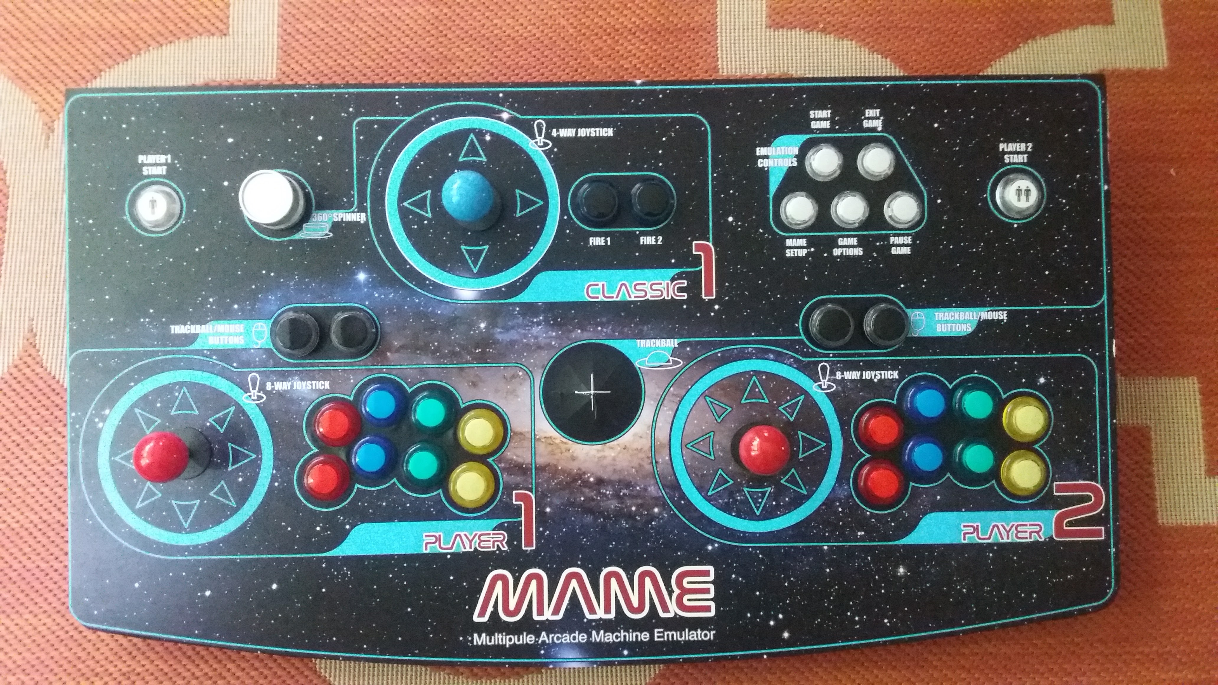
Next I stuck the control panel sticker on. TAKE YOUR TIME WITH THIS. Do not rush it. The GameOnGrafix.com website says to practice this a few times to get the feel of the material and I couldn’t agree more with that. Before you remove the adhesive backing, just practice to make sure you are lining up with the cuts and the button holes. You’ll have to trim the sticker likely, so make sure you hold it up to the control panel you cut t make sure it lines up perfectly.

20170422_223141 screen-shot-2017-04-04-at-11-01-03-am

After that, you’re free to start installing buttons and joysticks. I was SO excited to get to this part because it was finally taking shape. And my daughter had a ton of fun messing around with it even though she had no idea what it was.

20170425_180253


Building the sides of the box

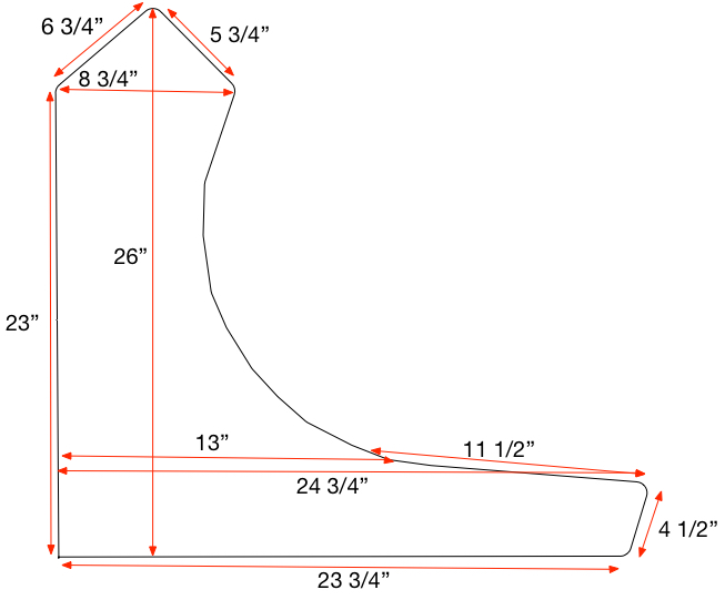
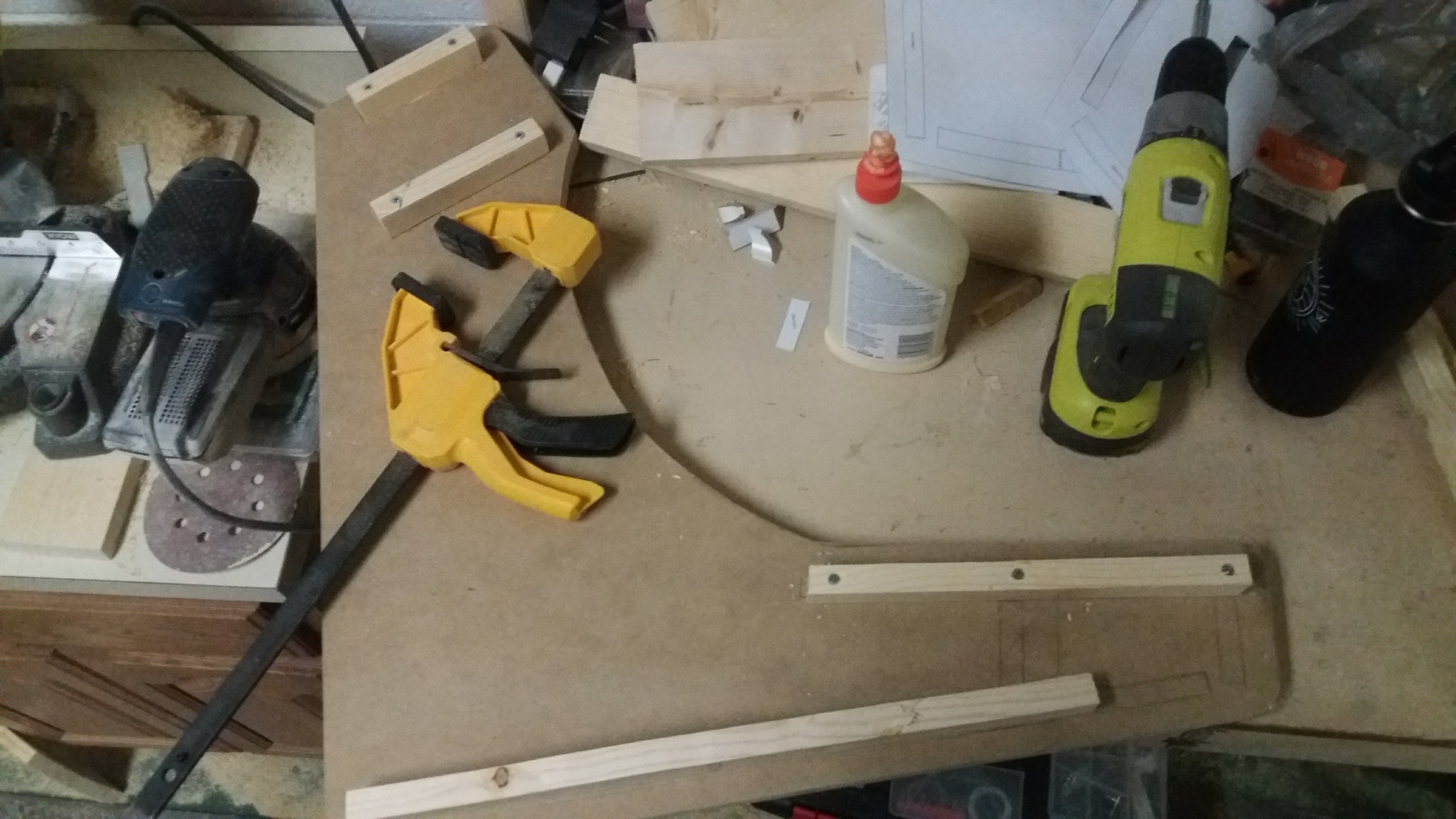
I still hadn’t realized at this point that the control panel was so large that it made my monitor size that I planned for seem like a dwarf scale monitor (sorry, but I’m not Tyrion Lannister). But I did know that the previously planned sides of the box weren’t going to be long enough to support the control panels depth. So my previous template for the sides looked like this:

20170302_101118

This was taken from the StarCade templates on this site. Here is the PDF I used in case the link changed.

A few things on this particular template. All I really used it for was the general shape of the sides. I felt like the baton placement wasn’t ideal for my setup, so I only used the bottom and the back baton guides. The rest of the batons, I placed using this image as a guide taken from this PDF:

screen-shot-2017-07-31-at-1-29-36-pm

The other thing that I liked about the above plans was how the curve of the lower part of the side was and how the small front part of the sides leans in towards the base of the side. It just seemed like a nicer, sleeker design. So I ended up using the StarCade template that I posted above, combined with the batons and front panel from the WeeCade. It’s the control panel area of the sides that I had to elongate. Unfortunately, there isn’t a design or template for this. I just had to measure a longer area for it to match my control panel. So, having said that, I’d say to complete your control panel first, so then you can measure the exact depth you need for the side panels.

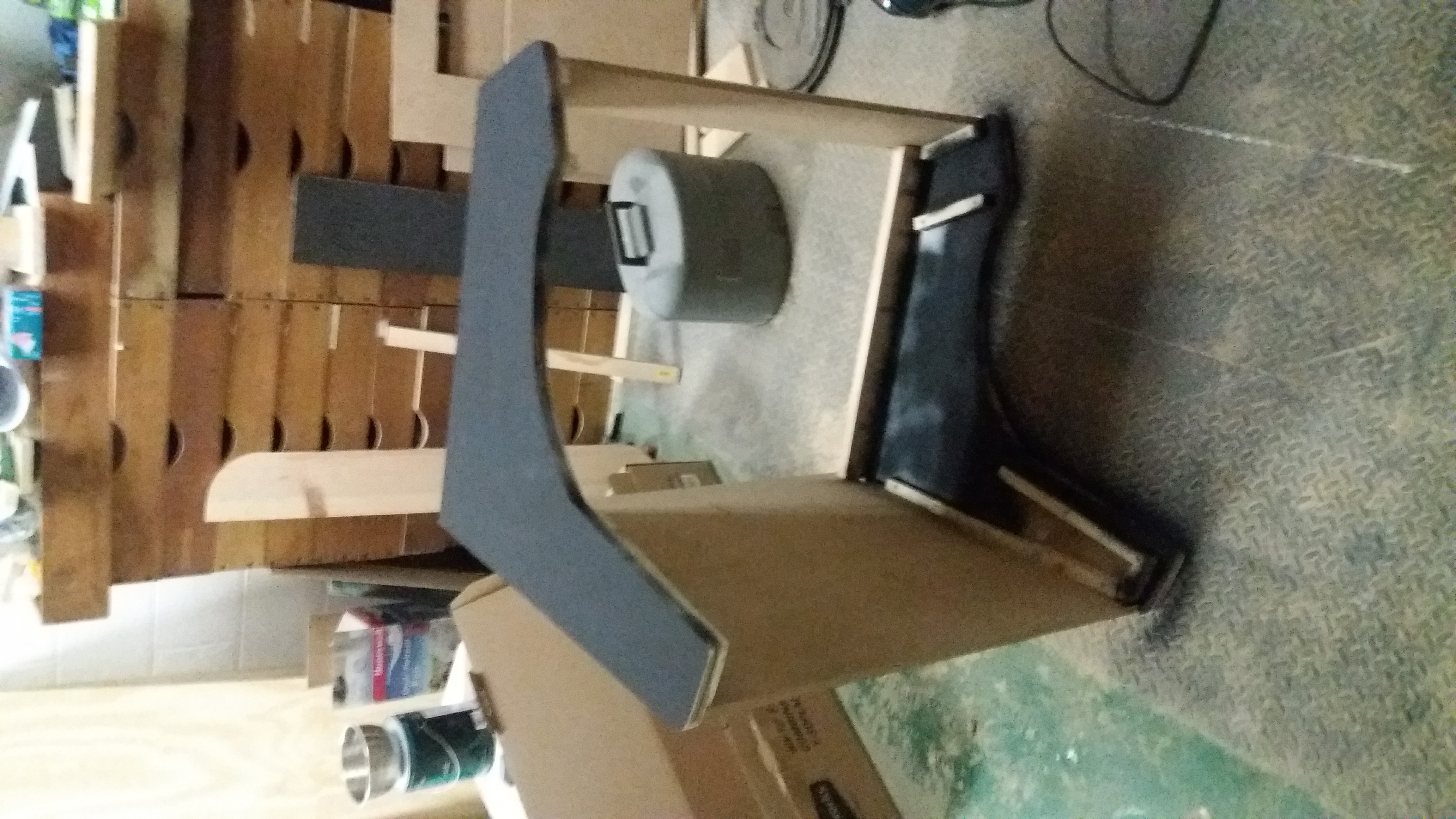
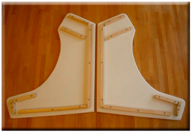
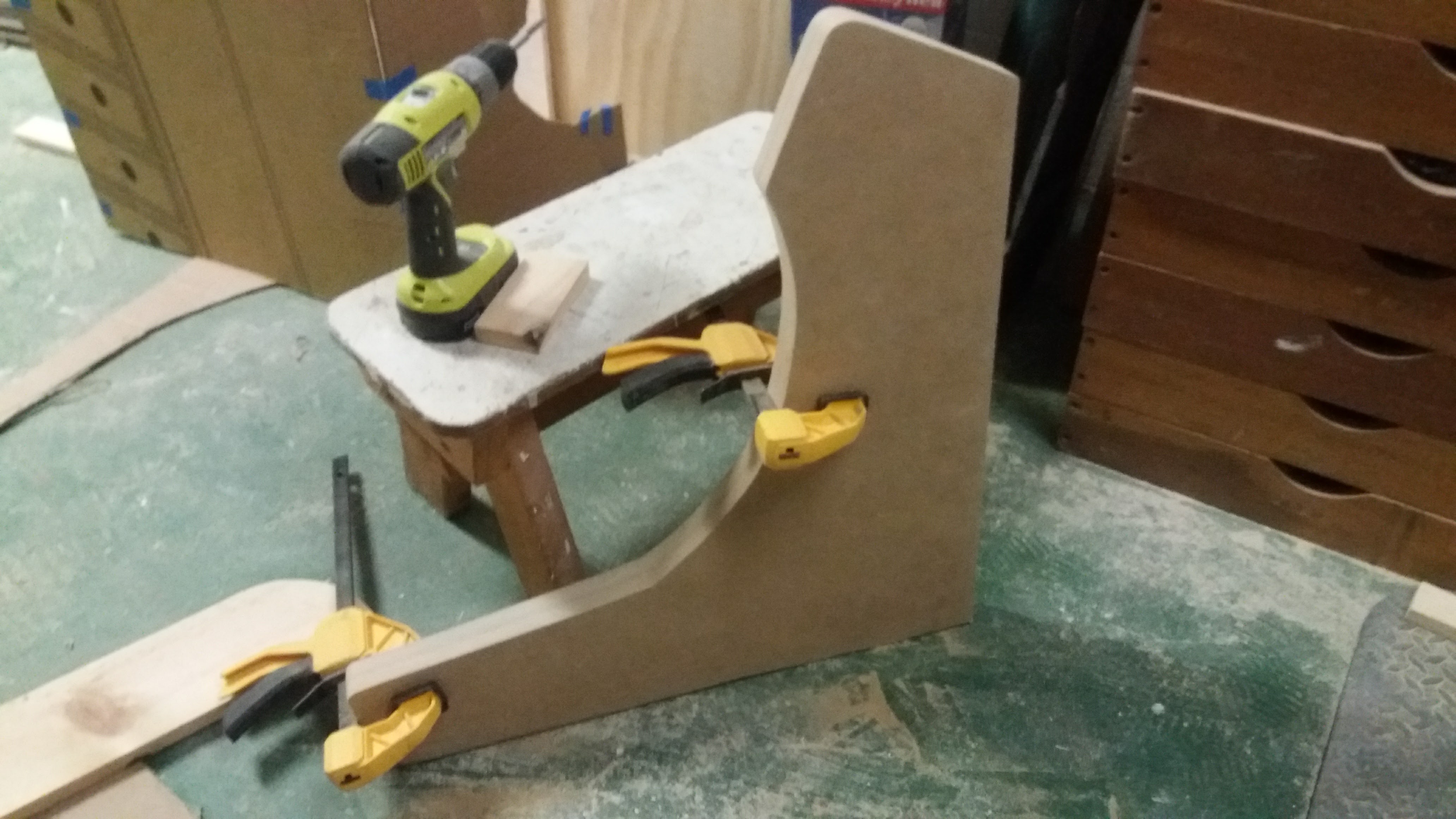
Here are my cut side panels and batons:

20170313_125001 20170313_115454


The back and bottom of the box

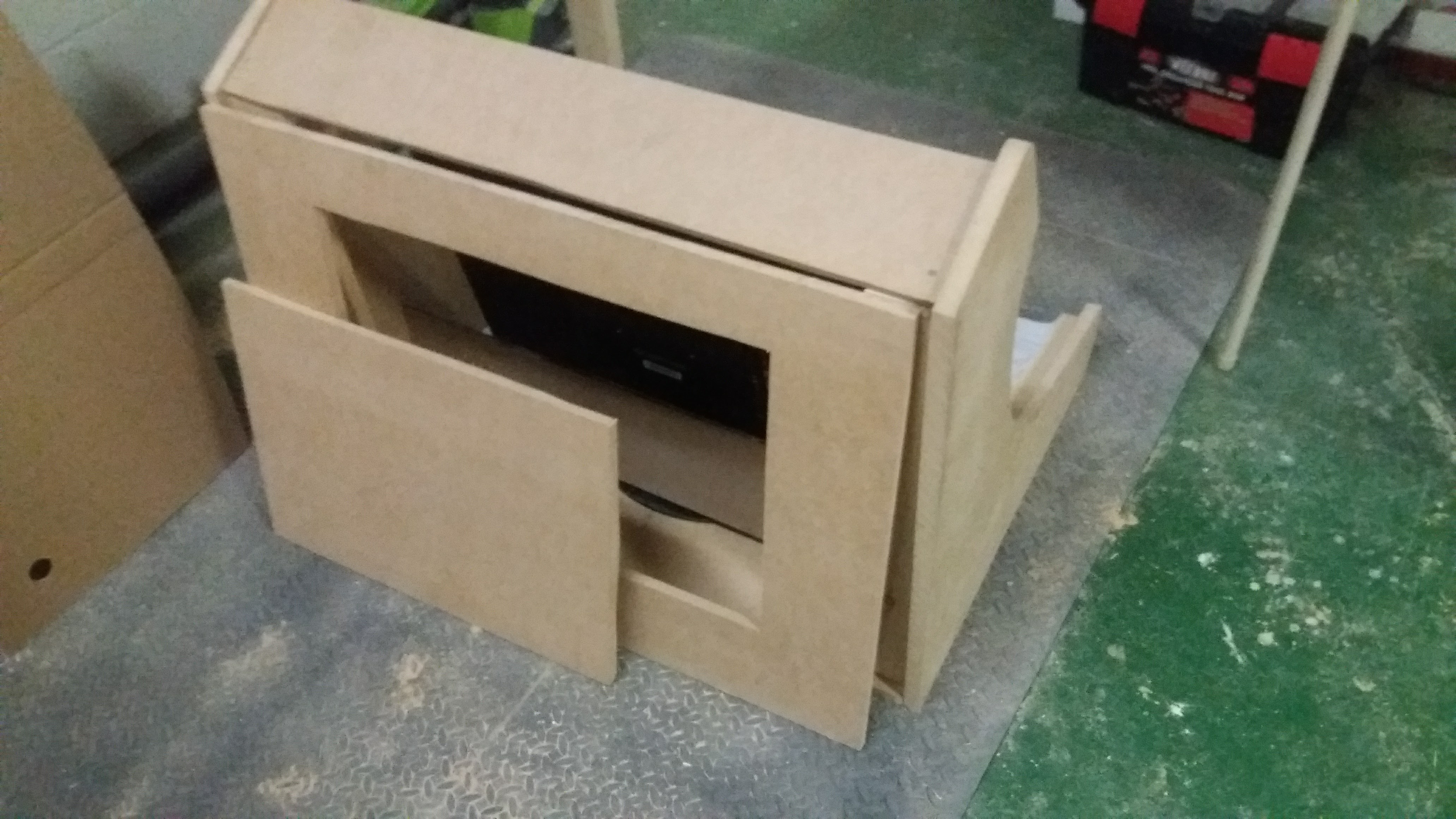
The back of the box could have been done a million different ways probably. I knew I may need to eventually get into the back of the box to fix things or replace something. In hindsight, I wish that I had made it slightly easier to remove the control panel without messing anything up. Granted, it really just slides out of the case, but I wish I had put hinges on it to flip upward or something. There are few things in the back that I need to access as the Raspberry Pi and USB hub sit directly under the control panel.

Anyway, I just bought some hinges and a lock for the back and cut an opening. Keep in mind that there are batons on both sides that the back has to fasten to. You can see in the middle picture below that I made the back batons much larger to support the back and the constant opening and closing of the door as well as supporting the top part of the arcade and helping to support the monitor weight.

20170405_122020 20170405_122029 20170511_141733

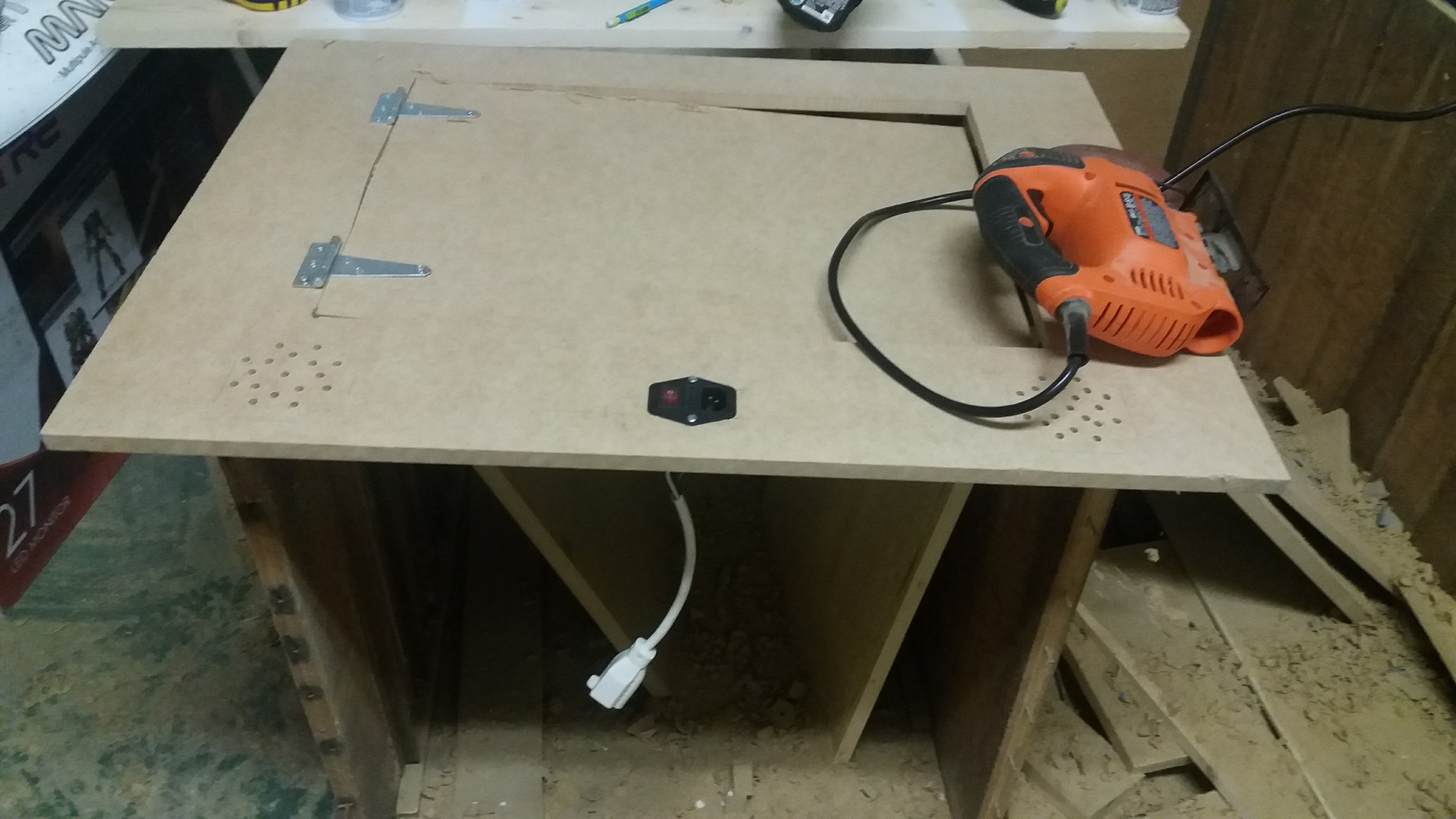
Nothing fancy about the bottom or the top. I simply cut the MDF board to fit the entire footprint of the box based on the monitor size. At this point I realized I needed a larger monitor. It’s a 27″ monitor that is pictured above.

Update: I’ve gotten a few questions about how to cut the back door out of the board. I used a drill to make several small holes in the corner of the door area. When you have a hole big enough to put the blade of the jigsaw through, then you should be able to start cutting along the lines that you marked off for the door. The door size should be big enough for you to reach into and tinker with the wiring. Honestly, I ended up making it easier to lift the control panel out and very rarely open the back door. My Pi and USB hub sit under the control panel rather than in the back. There is just more room for cables and it doesn’t turn into a rats nest.

Power outlet

Something that I decided, after doing some research, was to do my own wiring for the power plug and use a power strip with USB plugs on it to power some things rather than having to run cables up to the Pi or to the USB hub. This ended up being a really good idea and I’d recommend it if you have USB cooling fans or LEDs.

20170312_220555 20170312_220609 20170312_220513 20170312_220541

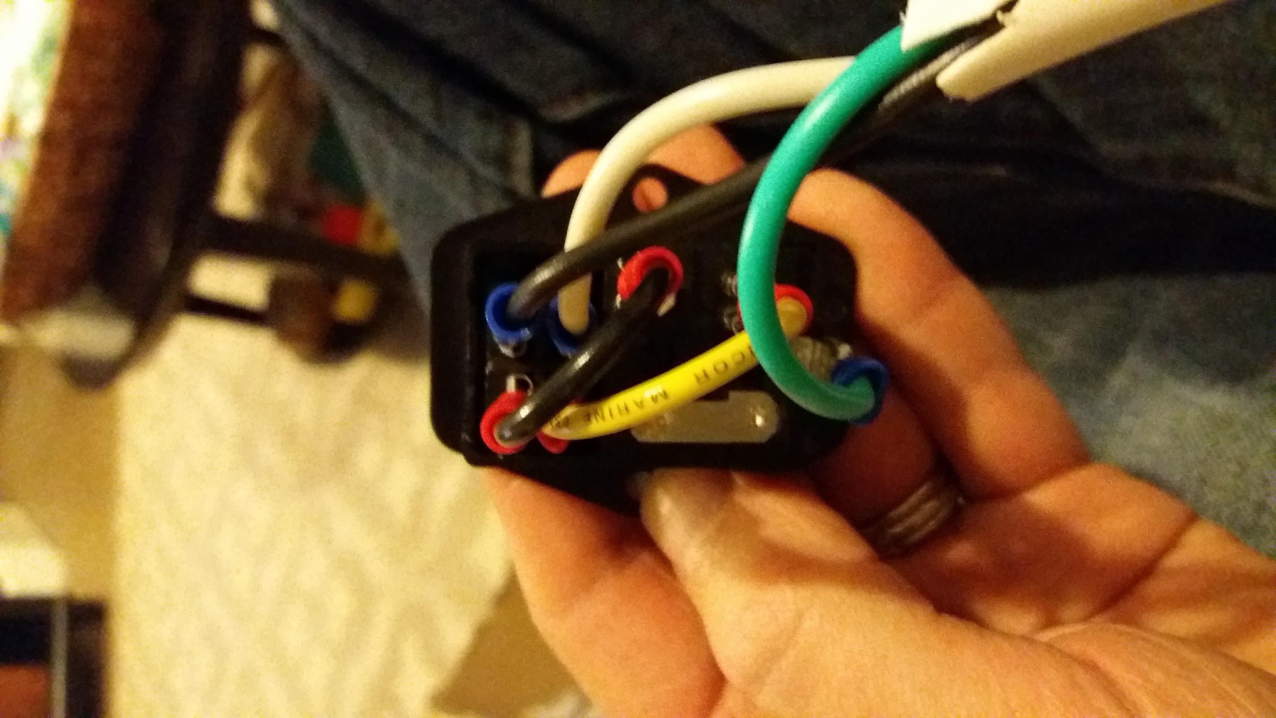
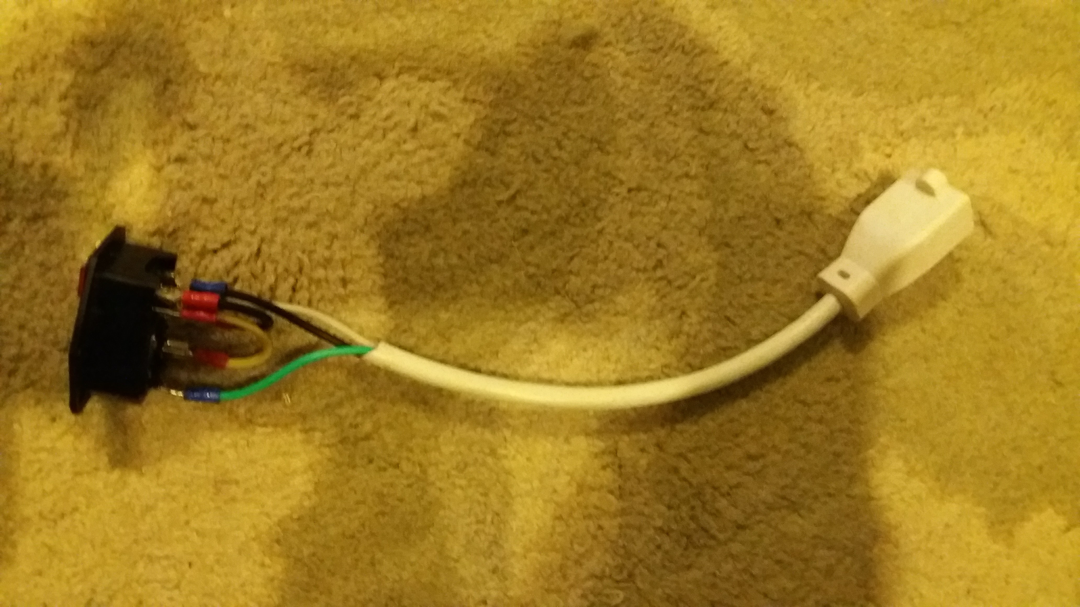
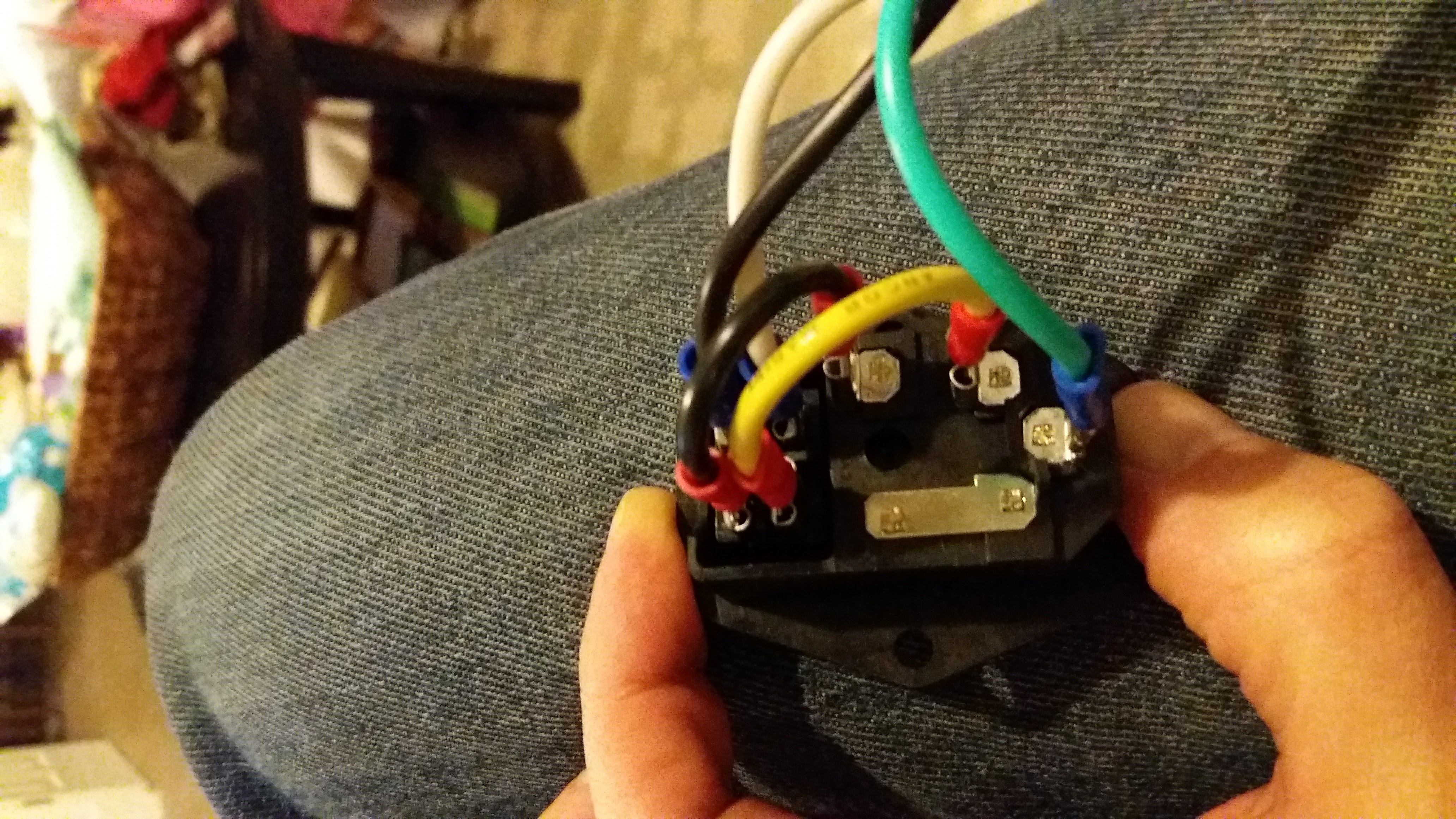
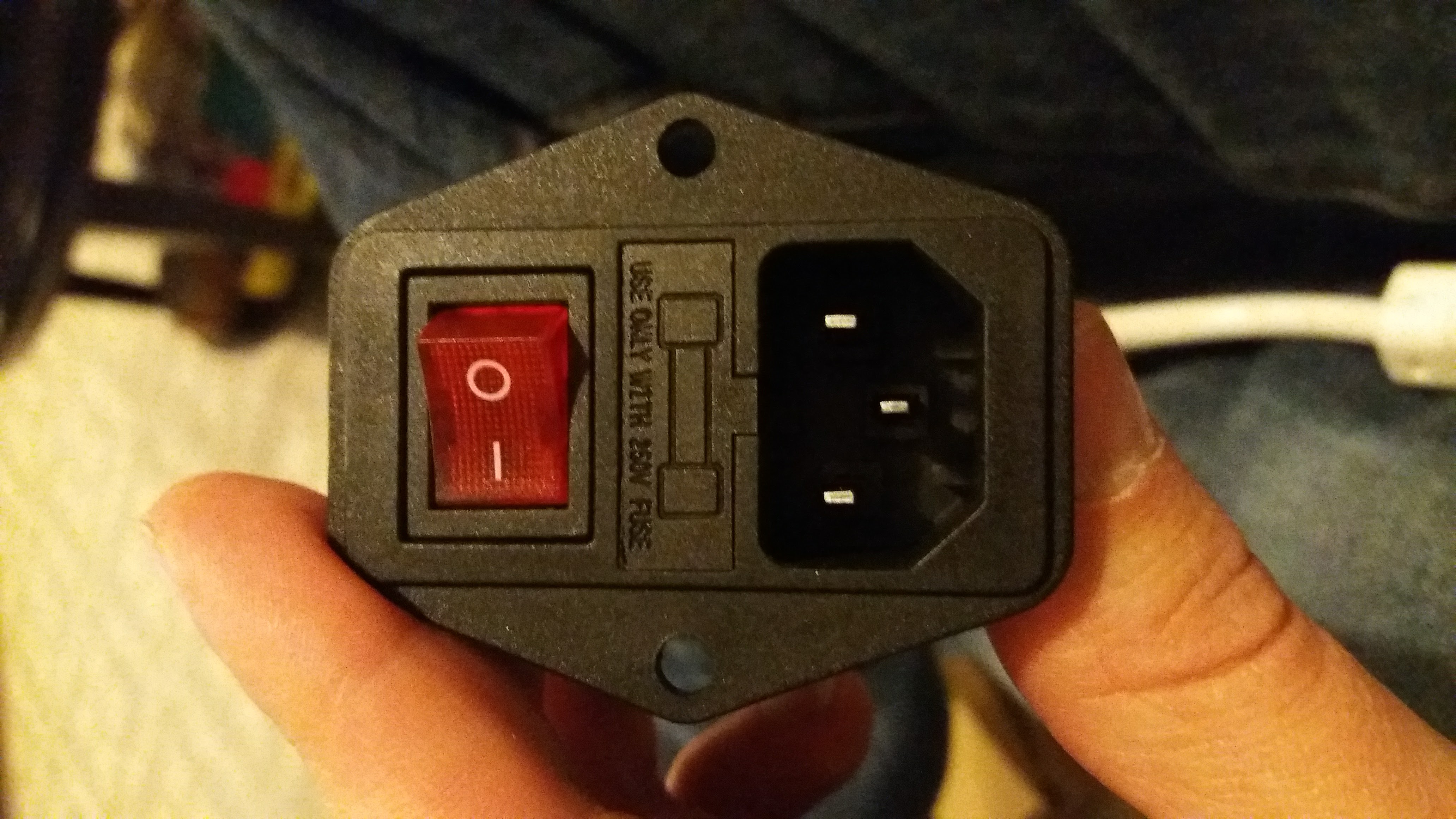
You can see in the back and sides section of this post, the power adapter hanging down after I installed it. I simply cut the end off an old extension cord that we had and used that. It made a lot more sense to do that than ruin the cable to an expensive power strip. Hopefully these images will help people wire their power adapter plug the correct way. It took a lot of research for me to find the correct way. Before I plugged it up, my dad (thanks dad!) helped me test it as he is much more familiar with electronics than I am.

Painting the sides

With both of the sides primed with KILZ, I opted for a really heavy lacquered finished. I just used spray paint in a vented area. I probably put about 5 coats on each side. About 2 cans worth probably. Make sure that your sides are level because the paint will run a little if it’s not. Also make sure there is no breeze or you could get wrinkles or debris in your paint.

I painted the sides with a flat black paint first just to make sure I was ok with the color choice and to offer a little more primer.

Here are the sides attached and painted:

20170422_134814


Here’s the third part of the tutorial.

Building a Bartop Arcade Machine – Part 1

bartop-arcade

For a long long time, I’ve wanted to build an arcade machine of my own. I researched doing it about 17 years ago, but the cost and the time weren’t something that I had (and I guess I still don’t).

Since about 1998, I’ve been using the MAME (Multiple Arcade Machine Emulator) program to run ROMs (video games) of all of my favorite games from the 80s and 90s. So the really really tricky part of building the program to run the games has already been done.

But what about the computer to run the games on?

Advancements in technology have made it much much easier to build a low cost, high functioning arcade machine. The main issue that I kept running into was needing to build a mega computer with a large computer monitor to actually play the games on. 20 years ago, that would have been extremely expensive. But now that we have credit card sized computers, such as the Raspberry Pi, the cost is significantly lower.

There are dozens and dozens of plans for bartop arcade cabinets online, but none of them were exactly what I wanted. So I decided to make my own design from a combination of different designs I found. One problem that I discovered is that all of the bartop arcade machines that were built for two players were actually very crowded and having two grown adults playing at the same time would basically have them touching shoulders with no room to move at all. So I knew I would have to make mine much wider than any other designs.

First, here is a video of my finished cabinet:


So….let’s get right to it.

Parts/Tools List

  • Raspberry Pi 3
  • MDF Board – Both 3/4 inch and 1/2 inch (get a few in case you mess up)
  • A monitor – In this case, I went with this Sceptre 27″ Monitor
  • Micro SD Card – This depends on the image that you use and how many roms you want to load. I’m using a 128 GB card. We’ll get to the images and roms later.
  • Arcade buttons and joysticks – There are many to choose from. I went with these packages with 2 player joysticks, and another single player joystick since I planned on having 2 players, and an analog controller for analog games. The all come with buttons too!
  • Speakers – These Amazon speakers are great and easy to take apart.
  • Power Strip – I love this power strip (ISELECTOR 4-Outlet Surge Protector with 4 USB Output Power Strip Charging Station) because it’s got USB plugs in it as well. Not everything needs to be plugged into the Pi, so I went with this option and it’s been great.
  • A router
  • This router cutter for the T Molding – Whiteside 6700A Slotting Cutter 1-7/8CD 1/16CL 5/16Bore 3Wing
  • This router bit for the cutter – Whiteside Router Bits A200B Slotting Cutter
  • Screws. Get an assortment 1 inch, half inch, small, long. You never know what you’ll need for this.
  • Drill
  • Jigsaw
  • Circular saw or Skil Saw
  • URBEST Inlet Module Plug 5A Fuse Switch UR and CE Certification Male Power Socket 10A 250V 3 Pin IEC320 C14
  • USB & 3.5mm Dash Flush Mount Cable
  • 3ft HDMI Cable
  • Player 1 and Player 2 buttons – I bought these and they work well.
  • USB Hub – Here is a list of USB hubs that work with a Raspberry Pi. I’d suggest looking at it because I learned the hard way that not all hubs work. Don’t buy a USB 3.0 hub. Make sure it’s powered.
  • Marquee Light – I got this one and it’s very bright and works great.
  • T-molding – There are all kinds of colors here
  • 2 Spade Drill bits (if you use the buttons I used): 3/4 Inch bit and 1 1/8 Inch bit. This is to drill the button holes.
  • A dust mask
  • Eye goggles. Seriously. Get these and the dust mask. MDF board puts a lot of particles in the air when you cut and some of it is extremely bad for you. Plus it will irritate your eyes and lungs.

If you do my type of control panel, you’ll need all of these additional parts:

  • Trackball
  • Trackball LED – The LED module comes with this trackball.
  • Spinner
  • 25 Cent buttons with lights – Bought these and they are great!
  • 6 additional arcade buttons – There are all kinds here
  • LED Wiz (to light up the trackball LED)

I ordered my graphics from this place and they are amazing, sharp and vivid.

Prepping the Raspberry Pi

Raspberry Pi’s are really neat little things. You can do so many things with them. I’m running a development server with 4 of them, and I run a Plex server with another one that host thousands of movies online so I can watch them from anywhere.

We’ll be using RetroPie, a retro gaming emulation operating system specifically for Raspberry Pi, to transform the Pi into your central computer for the cabinet. Not only does RetroPie play arcade games, but it also plays NES, Super NES, SEGA, and a bunch of other systems. It’s pretty incredible.

Depending on the size of your micro SD card, you’ll want to hunt down a RetroPie image. There are tons listed here: http://www.arcadepunks.com/retro-pi-downloads-page/

I’m not a fan of downloading things through online downloading companies like MegaDownloads. Most of them will charge you for large downloads or at least want you to sign up for an account to access anything. So I prefer to use the torrent links. I’ve set my Pi up to use Rey’s Image. Here is a magnet link to the sd card image. It will likely take 5-8 hours to download the .img file because they are huge. There are lots of different RetroPie images online if you just search for them. I’ve tried a handful and Rey’s Image is by far the most solid build and is almost problem free.

Once you download the .img file, you’ll need to transfer the img on to the SD card. I’d highly recommend either the Apple Pi Baker or Etcher to transfer your .img file to the sd card.

After you transfer the image to your SD card, you should be able to put in the Raspberry Pi and fire it up. For some folks, that may be enough. You could easily just hook that up to any TV and attach your controllers to your Pi and be done with it. But for us, we’re building an arcade cabinet and doing things the hard way. 🙂

Blueprints

As I mentioned before, I wasn’t able to find the exact blueprints that I wanted, so I elongated parts of various blueprints and created my own layouts for the cabinet.

Here are some blueprints that you can print off and cut from. You’ll likely have to print these off and tape them together unless you have a large format printer:

My cabinet has a deeper marquee area by just an inch or so, and the control panel area is deeper by about 10 inches to accommodate the trackball, spinner and the extra joystick. It’s also much much wider than most bartop arcade cabinets you’ll find online.

Update
I get a lot of email about my side panels and measurements, so I’ve finally gotten around to creating these. They aren’t to scale but they are pretty close. Most of the measurements are pretty accurate, but it’s hard to get absolute measurements because of the curves on the corners.

arcade-plans


Here is a PDF of the plans.

I did not include the curve radius on the front part of the side panel because I totally freehanded this. Basically what I did was cut all part of the side panel except for that curve. I trimmed it so it was pretty close to what I wanted and then sketched the curve. Then I cut it with a jigsaw and used a file to make it smooth and even.

The control panel blueprints are a completely different issue. That depends on a lot of things. Do you want MAME control buttons? Do you want coin buttons, or player start buttons, or both? Do you want a full 8 button control panel or just 3-4 buttons? Trackball? Spinner?

One of the first thing I would research is the number of buttons your favorite systems use. In the end I opted for 8 buttons. I’d rather have too many, than too few and not be able to play a certain game. Plus…and I just realized this, the more buttons you have, the more you can program to do different things, and the less you have to depend on a keyboard. Check this page out for all of the different system button layouts.

screen-shot-2017-04-04-at-11-01-03-am

If you want the exact Photoshop PSD control panel file I made, here it is. It’s huge (over 200M) and you’ll need the NASA fonts. I designed this entire thing myself, and after all this time, I just realized that I misspelled multiple (multipule). I’ll post the marquee design later.

Before you cut MDF board…

Before you start cutting MDF board, it would really be helpful to make a full scale model to help you get all of your measurements. Make it out of cardboard so that you can draw on it and cut it easily. You’ll want to also print out your templates for the control panel. I setup all of my buttons and played a few games just to see if I like the layouts. I ended up changing the button layout 3 times until I found the one that I liked.

20170306_182952 20170302_101118


20170306_120601

You can see on the first photo that the bottom part of the side of the cabinet doesn’t extend far enough out to support such a large control panel. So I knew I’d have to customize the sides. You can also see where I traced the blueprint for the marquee area on the side, and how I extended it out further to accommodate my speakers and lights.

Here is the second part.