Posts By: Jason Glisson

Tips for traveling to, around, and from Peru (plus some helpful COVID travel tips)

IMG_20210803_132546
Having just returned from Peru, my wife and I learned a lot of lessons and picked up some tips while we were there that I thought I’d share with you.

  • Altitude sickness is a real thing. For some people it is just a mild headache. For others, they have to lay in bed for at least a day. My wife and I were just fine the first day. Drink a LOT of water. And I mean bottles and bottles of it. This helped a lot. I took an ibuprofen and was fine. Someone on one of our tours had to leave their travel companion at the hotel because she felt so bad. Hotels also offer oxygen tanks if you need it.
  • Bring wet wipes and toilet paper to use in bathrooms. Most Central and South American countries don’t throw toilet paper in the toilet.
  • At Machu Picchu, if you are planning on not using a guide, reconsider this. We were planning on not using a guide the second day, but one approached us and was able to get us to the front of the very long bus line and the very long park entrance line with very little wait. He spoke very very good English and was very informative. He gave details and information on things we would have definitely missed. Choose your guide wisely though. A couple that arrived at the same time as us picked the first guide they saw and I overheard him trying to explain the ruins and he just didn’t know the words and admitted that he didn’t know the English words. While I wish my Spanish was better to speak in their native tongue, you can’t fault the guide for just trying to make some money.
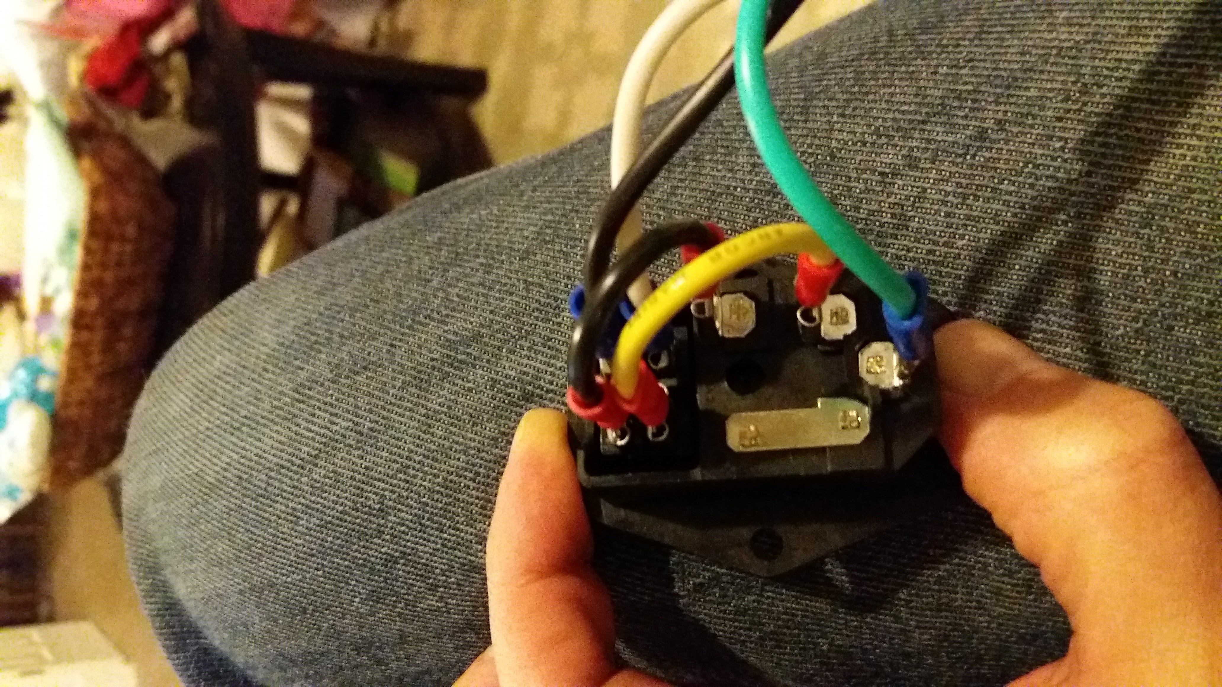
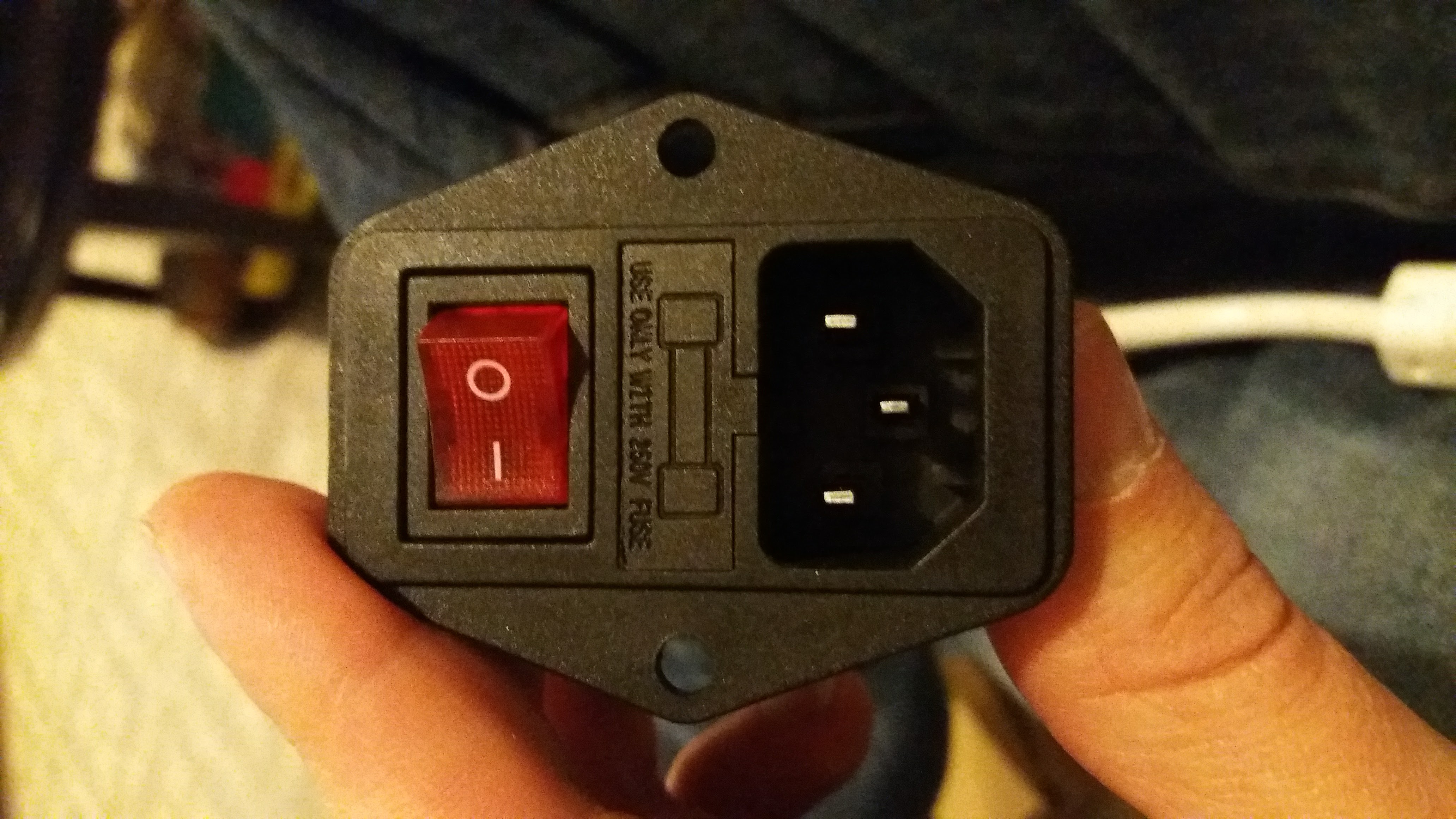
  • Peru’s voltage runs at 220v. For most phones and tablets, you can charge directly on their grid. For things like laptops, curling irons, or anything else, you’ll need to check the voltage or just use a voltage converter. This is NOT a simple power/plug adapter.
  • While shopping at markets, feel free to offer slightly lower prices and haggle. My wife was able to get some souvenirs for 10 Soles cheaper by just offering the deal. In Aguas Calientes, the town nearest Machu Picchu, there is a HUGE market there. Get lost and see what you can find and make some deals. It’s just outside the train station gate.
  • Splurge for the Vistaview Peru Rail train into Aguas Calientes. The scenery is amazing and beautiful. They also explain things you’ll be seeing in both Spanish and English as well as announce train stops. There is sometimes entertainment. Our train leaving Aguas Calientes had a person dressed as a demon that danced through our car.
  • If you can help it, don’t check your luggage. My luggage was lost for our entire trip and I got it back only at the end of it. Since we were in Cusco briefly and left to goto Aguas Calientes, there was no way to get my luggage to me quick enough so our hotel held it for us with the help of our amazing travel agency. I ended up buying some nice alpaca sweaters and tourist shirts, but I had bought an entire new wardrobe for our trip that I didn’t even get to wear. It turned out that I didn’t need as many clothes as I originally packed anyway. Which leads me to my second point….
  • Don’t bring as many clothes are you think you need. Leave some room for souvenirs. And if you need to you can have your laundry done at your hotel for pretty cheap. I had all of my clothes washed and folded for $25. That probably saved me $50 in clothes.
  • You’ll find alpaca clothes literally everywhere. Most in the cheaper markets are what they call “maybe” alpaca and not “baby alpaca”. Meaning, it might be baby alpaca fiber but is most likely mixed with synthetic material. We bought both maybe and baby alpaca sweaters. And to be honest, I love my “maybe” alpaca sweater the most. Baby Alpaca fiber is cool to the touch and ever very soft. Train yourself once you see real alpaca fiber, and if this is something you want to chop for, make sure it’s authentic first. Most street markets don’t sell real, 100% alpaca fiber clothes.
  • If you are in the town square of Cusco, and you are dressed like a tourist, expect to be asked to buy things literally every 5 seconds. From local artwork, to jewelry, to shoe shines, to asking to eat in various alleyway restaurants, etc etc. We actually did buy some artwork from several people that we really liked. Having said that, when we sat on a bench in the city center of Cusco, we were swarmed with people asking us to buy things. While we were trying to explain that we just wanted to sit and enjoy the view or that we just didn’t have anymore Soles (which was true), someone stole my wife’s phone that she had sat down beside her on the bench for a second. So just take care. The crime is very low in most places and we never once felt in danger or threatened. This was just a poor souls opportunity to take something they though might be able to make them some extra money.
  • Speaking of restaurants, there are several in the Cusco town square that have fantastic rooftop views of the city. Look around at a few before settling and make sure you have a great view. We ate at two different ones, both with great views.
  • Some hotels have all kinds of perks and amenities that aren’t listed on their website. One of our hotels have baby alpacas on the property that you were able to feed bottles to for free three times a day.


IMG_20210802_102104
Things were very different from any other time in Peru because of COVID restrictions. Peru has taken COVID very serious as of lately and enforces masks everywhere. Here are some of the things that you’ll need to know:

  • Before entering the country, you must have a negative COVID test. This can NOT be a rapid test and should be a PCR test. You’ll need this to be 72 hours before your departure and you will be asked to show proof multiple times both in the US and in Peru.
  • Before leaving Peru you will need a negative COVID test. They have their own test that they do and the results will only take 15 minutes.
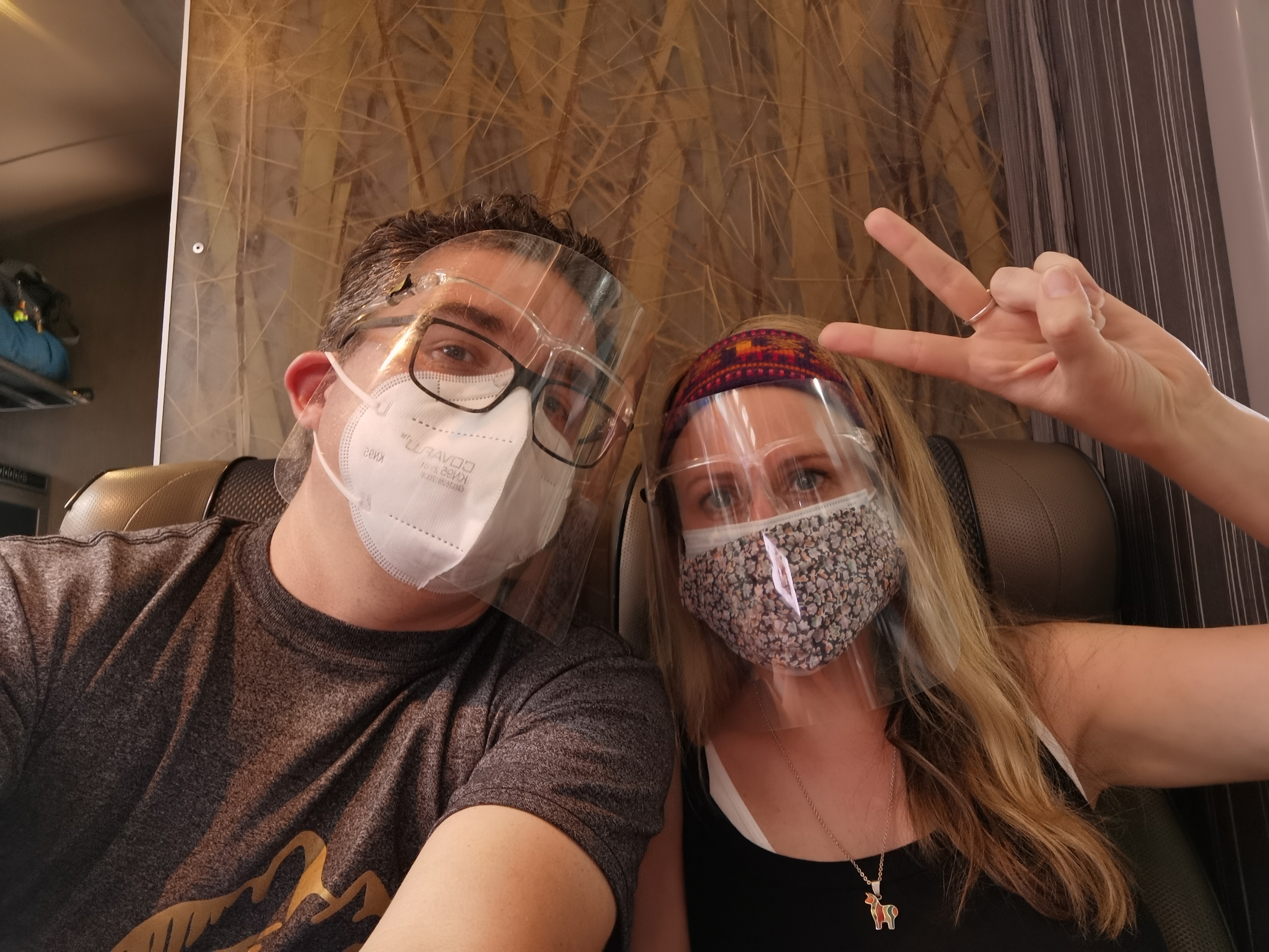
  • On the flight into Peru and out of Peru, you will have to wear two face masks. If you remove those during your flight, you will be met by police when you land. Most flights give three warnings and announce this over the speakers several times. When we landed in Atlanta from Lima, Peru, a gentleman was met by police after being warned three times and then having an altercation with a flight attendant over wearing his mask.
  • While in Peru, expect for everyone to be wearing masks at all times. For most buildings, before you enter into the building, your temperature will be taken.
  • For trains and buses, your temperature will sometimes be taken, but at all times, you must wear two masks and a face shield. If you don’t have a face shield, you’ll need one for other occasions as well. We went to the Regional History Museum and Cusco and had to wear one as well as two masks for the entire visit.
  • Hand sanitizer is literally everywhere. Use it anytime you see it.
  • If you’re visiting Machu Picchu, taking your masks off there is strictly forbidden, though, most guides will work with you to try to time face masks removal for photos. If you are seen by one of the many MANY guards around the park, you’ll be yelled at and told ” if you please, put your mask back on”. The second day where were there, all we heard was “POR FAVOR!” being yelled everywhere along with a whistle or hand bell ringing. So just take care here. If they warn you a few times and you ignore them, you’ll be asked to leave.
  • While ordering food, keep your mask on. When your food comes, you can remove your mask, but if you aren’t eating or are finished eating, put it back on.

IMG_20210804_162103
We loved Peru and will definitely be going back. There is so much to see. The food is so good. The people were very very nice.

Feel free to contact me with any questions.

Building an Arduino Nano Lightsaber – Part 1

lightsaber
(This blog post is a work in progress)

Come on. You KNOW you’ve always wanted one. I certainly did. I bought a rather high end lightsaber several years back from Saber Forge, which only lights up red, but is really amazing and everyone is always impressed with it. It’s customized and combines several Star Wars based sabers except for the grip. I haven’t ever taken it apart to see what was in it as far as components, but the speaker is extremely loud and it always sounds great.

13119970_10103191884844203_5870625522556344812_o 13047819_10103191884854183_443946423984511142_o


I’m in the middle of building an Arduino Nano Stormtrooper E11 blaster and my wife asked me if I thought I could build the kids some lightsabers so we could feed their new obsession with Star Wars. My initial reaction was “Wow…..my wife just asked me to build a lightsaber for my kids!” I was pretty sure I could, but hadn’t looked much into it yet. I knew there were places to get Arduino lightsaber setups so I started researching and found that there were MANY ways to build a DIY lightsaber. There are so many videos of people building them. There’s actually a pretty nice open-source community for lightsabers.

Arduino Nano’s are super cheap and all of the components for the lightsaber could probably be purchased for around $25-$35 dollars. I’ve seen a lot of people using Proffieboard which is a custom board just for making lightsabers. These usually run $40 – $50 on the internet, but there is a big community for them. Eventually I may try those out, but for now, and since I have a bunch of Arduino Nanos, I want to try a Homebrew board.

Let’s get to it!

Parts list:

  • Arduino Nano
  • MPU-6050 Accelerometer
  • DFplayer
  • 2-16GB SD Card
  • Neopixel light strip (assignable WS2812B RGB)
  • Two momentary buttons, non-latching type (my example uses non-LED buttons)
  • 2W 8 Ohm Speakers
  • Resistors (haven’t figured out all the types yet but I’m using some 15k and 150k in various places)
  • Wire
  • 5v power supply
  • 18650 battery

A Few Notes

For the most part, I followed the Wiki on FX-SaberOS but I kept hitting a LOT of “gotchas” and small issues here and there. Here’s a running list of the things that I’ve worked through. I hope it helps someone.

  • One thing that I didn’t see documented anywhere is that you can not power this setup with a USB from your computer. You can get part of the way there, but the speaker and Dfplayer will not have enough power from your USB to make all components work. Normally I just use the USB since you have to use it to transfer files. I try to avoid plugging and unplugging a lot of the time because I want to avoid accidentally pulling a wire out.
  • Make sure that you get a 5v power supply. Without it, your speakers will not work and you’ll likely get a “bep bep bep bep bep” sound. This took me a long time to figure out because it’s not really stated in the documentation but it’s “implied” by showing a battery connection in the FX-SaberOS wiring for the homebrew pixel blade saber. I found a 5v power supply in a junk box and just cut the ends off and it worked perfectly.If you have a 18650 battery on hand (which I did not and still do not), probably best to try to prototype with that.
  • Several people have reported having buzzing or other sounds coming from the speaker. Putting a resistor on the RX pin solves that problem for me. I found that listed on a few DFplayer forums. They actually said to put a resistor on both the RX and TX pins, though just the RX worked for me. The same forum also mentioned that using both of the grounding pins on the DFplayer module can also help.
  • The FX-SaberOS schematic is well done, but I found it a little hard to follow and not easy to tell which things need to be connected together, or to resistors, or how to power it with just standard buttons. I like the LED buttons, but I don’t have any and don’t really care to spend the money on them right now, so I’ve made a new schematic (below) showing standard momentary push buttons. These sabers are for my kids and, well, they already light up. They won’t miss an LED button.
  • For the LED strips, I’m just using one right now for testing, but once you have both (installed back to back), you can wire them up exactly as the schematic shows. Otherwise,  just pretend the one on the bottom doesn’t exist.
  • When you connect the 5v power, connect it straight to the Dfplayer first, and then bridge over to the positive power line on the breadboard to power everything else. You’ll find that your setup runs much better if Dfplayer has enough power. This will also prevent you from having issues with the sound while you trying to figure out the config menus. For a while my sound kept cutting out because I wasn’t getting enough power to it, and setting it up this way fixed that issue.
  • For Mac users, make sure that the SD card doesn’t have metadata files and dot files on it as you are moving files over. The only way I could get this to work properly for me was to manually create the folders and put the files in them one at a time. The sound files have to be perfect or nothing will sound right and the config menu won’t make sense. You’ll need to go to System Preferences > Spotlight > Privacy and add your Sd card to this list so that your computer will stop creating these “Spotlight” files on the card. If you don’t do this, it will create them again as soon as you remove them. If you’ve already removed them and thy reappear after you add your card to Spotlight, use rm -rfv .Spotlight-V100 to remove the file in a terminal window then rm -rfv .Trashes to remove the files you just deleted. The other “dot” files can be deleted the same way just be sure all that is there is the soundfont files and directories.

Schematic for Prototyping

lightsaber

Downloading the Code

If you haven’t already gone over to FX Saber OS’ github repo, go ahead and check it out.  There are some really good resources out there for this part. I stumbled on this video for transferring the files (which hopefully you know how to do) and a walk through of some of the configs that you can change for your setup.


Setting up the MPU

This step must be done before wiring up your components. The Wiki on FXSaberOS is pretty straight forward. I found that the jumpers for my breadboard didn’t work that well with my MPU so I went ahead and soldered wires to it. The startup will not move forward if the MPU is not configured or if it doesn’t connect to it and detect it working properly. The below directions are directly from the FXSaberOS page:

To use the calibration tool (either one):

  • simply download the tool
  • upload to your DIYino or Aruduino compatible board through the Arduino IDE with the Serial Monitor open
  • Ensure that your DIYino or MPU6050 is level to the ground in the position it will be in your saber
  • press any key to execute the script
    • make sure the board is stable and do not touch the board while the board is being calibrated
  • once the calibration is complete, press “y” to automatically write the calibration values to your board

It took several times for me get a “connected” reading on my board and that was only because the jumpers weren’t connected well. There should be an LED lit on the MPU when it is connected. In the serial monitor, you’ll see a running log of random numbers. That means it working.

Initial test troubleshooting

Once you get it all wired together, start trying to ignite the blade and see what happens.

Here are some troubleshooting hints that I worked through:

  • Once your connect your power, you should hear an announcement saying “DIYinoLightsaber”. If you don’t hear that, either your speakers aren’t working or your sound files are not setup correctly on your microSD card.
  • If you have a two button setup, you should be able to hold down the Aux button and entire into the Config menu while the saber is off. once you enter into the config menu, you should hear “Config Mode”. If you don’t hear that or hear something else, check your SD to make sure your files are in the right order and that you don’t have extra files there.
  • I’ve already mentioned the “bep bep bep bep bep” sound. If you’re hearing that, you probably have a power problem between the DFplayer and your Nano.
  • If you connect your setup and nothing happens, make sure you have an LED lit on all of the components. Check the MPU and make sure that is connected properly. If the Nano doesn’t connect to that, the software will not boot properly.

I’m in the middle of 3d Printing parts for these lightsabers, but here is the general idea of what they look like so far:

img_20210112_102321 img_20210112_102250


This is basically the top part of Darth Vaders saber hilt. The body is a 1 1/2 inch sink pipe. I’m working on a chassis and grips for it right now. I’ll cover the assembly in the second part.

Star Wars 3D Printed E11 Stormtrooper Blaster with Arduino Electronics – Part 2

(This post is a work in progress)

I’ve spent a few days looking over the two Arduino blaster plans that I’ve found and listed in my first post. While they are really well done and have some amazing features, I’ve found that I want parts of both of them and want to exclude other parts. So the best way to do that is to just do it myself and make this from scratch.

Here is my first attempt at a blaster light with an Ardruino Nano:


Basically what I wanted was something simple that was just a trigger and a light. I went a little further after this video and added a sound as well. The thing is, I haven’t found any plans anywhere on how to do any of this at its basic level. Fortunately, I’m a web developer and Arduino code is simple. But I can tell for other, this would be confusing and hard to figure out.

So what I’ve decided to do is make a few different files and repos that people can download that gets them “click and light” with no sound, “click and light” with one sound, and then the full build that I’m doing with lights, sounds, and all kinds of effects.

This the full schematic that includes lights and sounds.

nano-blaster


Parts list:

  • Arduino Nano
  • 3w speaker
  • Momentary button or push button switch. This will eventually be replaced by a limit switch on the actual gun.
  • Two 2K resistors
  • DfPlayer
  • A 2GB micro SD card (minimum of 2GB but can be bigger).
  • A NeoPixel strip or any assignable WS2812B LED strip. I used this one.

You’ll notice there isn’t battery yet. I haven’t gotten that far yet, so I haven’t figure out which battery I want to use. I may have to change out the resistors as well.

Code for click and light with sound: https://github.com/jasonglisson/nano-blaster/blob/click-light-sound/nano-blaster.ino

Code for click and light (no sound): https://github.com/jasonglisson/nano-blaster/blob/click-light/nano-blaster.ino


Star Wars 3D Printed E11 Stormtrooper Blaster with Arduino Electronics – Part 1

Stormtrooper

Since I was a kid, the Imperial Stormtrooper has always been the ultimate bad guy. I used to have two original late 70s Stormtroopers that I would always stage being the bad guys with my GiJoes or really any other scenario. I’m a huge Star Wars fan and I’ve always wanted to own a set of Stormtrooper armor and weapons. The Empire always did have the cooler vehicles and weapons to me.

I decided a while back that I had to build a Stormtrooper blaster, called the E11. I’ve started printing the parts today and it seems relatively straightforward. The blaster is based off a British made sub-machine gun called Sterling. It was altered for the film slightly and given a little more character.

After looking through tons of different models, and there are a lot, I settled on the one that most of the serious cosplayer use:
https://www.myminifactory.com/object/3d-print-star-wars-storm-trooper-blastech-e-11-blaster-rifle-by-blaster-master-72283

E11 Blaster


While there are probably more accurate models, this model looks like one of the better ones and has been hailed as one of the most accurate. If you really want to get very very accurate to the screen used models, you’d need to print out a full Sterling model, and then use the modify kit with the E11 accessory kit just like they did for the movies. That’s a lot of printing, so I’m settling for the one that I’ve mentioned above. One thing that I like about this particular model is that they give alternative parts depending on how you are building. In particular, the magazine casing has a port for a speaker and the alternate print is without this port. I’ll likely print both since I don’t know where my speaker will go yet. My blaster is going to have an Arduino Nano, speakers, and well as an LCD and bar graph. I’ll get into the specifics of the Arduino parts in a bit.

I don’t know that there is a model exactly like the one that I’m building on the internet, but it’s going to be pretty close to this one.

There are also some other modifications that I’m going to make, but that’s going to be a awesome when I get to it (in another post) because I don’t know that anyone else has done it and it’s going to be a ton of fun when I get it finished. I’m planning on adding a laser tag option. My kids are going to love that. I’ll make it play R2-D2’s dramatic sound (like when he gets shot) when someone gets hit three times or something. I’ve already started on the Arduino code for that.

This is really where I’m getting the Arduino plans and reading the discussion. It goes back years and you have to read all of the details:

https://www.whitearmor.net/forum/topic/19322-arduino-a-cheap-board-for-e11-blaster-effects/

This is a newer post about it:

https://www.whitearmor.net/forum/topic/46692-blaster-electronics-fx-blasteros-goes-open-source/

Essentially it looks like this in circuitry:

E11 Arduino Blaster

There are some big differences in the way that I’m doing it but this is basically how it will be connected. I may only have room for one speaker, but we’ll see. The speakers in his kit are much larger than mine, but from the reviews, my speakers are so loud that it shakes the gun. People have been using them as Lightsaber speakers as well, so that should be cool.

This second schematic has some additional things that I’ll be doing. I’d like to highlight the Neopixel that is in the barrel and the LCD display.

E11 Blaster Arduino


Arduino Project – FX-BlasterOS

Here is where it gets very technical. I’ll say that Arduino programming is pretty simple, but I’m a web developer so I understand how code works. It’s basically like Javascript and things are just a little more, well, clunky if you has me. But it’s still just basic code.

The project that I’m using is called FX-BlasterOS. I don’t know that a ton of people have been using it, but I’m planning on making a wide range of weapons using this. I may even start selling them on the side. Pretty fun side project to be honest.
https://github.com/Protonerd/FX-BlasterOS

If you interesting in this project specifically and don’t really want to learn all about Arduinos and what you can do with them, there are some pretty detailed instructions on setting up the project, though you’ll still need to learn quite a bit on the side.

There is also a full shopping list here, which I’ll likely update on my own site when I find the parts I’m using. Most of these parts will be the same.

Here is the beginning of my Arduino setup, though I’m also testing it out for the laser tag part. So far so good. I’ll have to figure out how to focus the beam for the IR transmitter. That might end up taking up the scope and I might just drop the idea of the LCD in the scope.

Arduino


The first part of my blaster is almost done, and then I’ll start trying to figure how the layout for my circuit.

E11 magazine holder


I’ll update when I get a little further along in this project. I also still have more to do on my Ghostbusters proton pack.

3D Printing A Ghostbusters Proton Pack – Part 3

I’ve got most of the 3D printed pieces put together now.

To keep them all together, I’ve glued them and then melted the edges together. For some of the parts that won’t be see on the outside, I’ve melted holes through the sides to join them a little better. The goal here is to minimize movement between pieces.

I’ve started to attach the brass fittings and hoses while paying careful attention to the color and how the hoses are positioned. Some of the close ups of the real, screen used packs from GB1 and GB2 have revealed differences in the hoses and brass fittings. So I made sure that I ordered the correct fittings for a GB1 pack.

I had ordered a package of hoses that were supposed to match the hoses on the proton pack from GB1, but noticed that the yellow hose was way too bright and not the right brand. So I found one on Ebay that is the right brand and shade.

To attach the hoses, I felt like simply gluing them into place with hot glue wasn’t going to hold very place very well if something got snagged on them (and I’m sure they will). So I used a screw inserted into the hose and screwed as tight as I could get it without breaking the hose. Then the end of the hose with the screw fits inside the fittings nicely. With some hot glue, it holds really well.


Using my soldering iron, I was able to melt the holes that we in the 3D prints so that I could screw the brass fittings into the part really easily. As the melted part cools, I can slowly start turning the brass fitting so that it forms a screw hole for the fitting itself. For the most part, I just hand tightened these and they feel like they’ll be secure enough to the pack where they won’t budge. I may dab some glue on them just to make sure.

The Proton Pack Wand

There are few Sci-fi movie pieces of equipment that are as recognizable as the Proton Pack. The key part of the pack, the wand, has many intricate parts, knobs, dials, tubes, etc. I started printing and buying aluminum machined parts for the wand probably before I even started building the pack. Eventually I realized I had the bulk of the parts and started laying them out to assemble the wand.

Proton Pack Wand parts

Proton Pack Wand parts

The first thing I did was start planning the placement of all of the knobs and dials. And there are A LOT. The wand was way more complex than I was expecting and just figuring out which knob goes where made me look at reference images for quite a long time.

dav

Sided knobs

Front knobs and Clippard

Front knobs and Clippard

Front knobs and Clippard

Back panel knob


Next I screwed the handle on the main grip of the wand after painting the grips black. They were originally a brown resin that I had specially made since the originals were brown resin with a black finish. I haven’t decided if I’m going to “age” the pack yet or not. The way that I’ve painted all of the parts, if there is a scratch or a chip in the paint, it should look natural and like normal wear and tear similar to the screen used packs.

Wand Handle Grip

Wand Handle Grip

Inside gun box attaching handle tube

Inside gun box attaching handle tube


Next I needed to assemble the wand tip, clear tube, and secondary grip. But there were a few things that I noticed after looking at the screen used wand. First, there is a wire running under the grip the entire length of the tube. Next, there is a bit of electrical tape here and there. I decided to loosely fit these items together because I’d likely need to take them apart when I install my electronics and when I finish my wand pop mechanism which I’ll discuss next.

Clear tube assembly

Clear tube assembly


Wand Pop Mechanism

If you’re going to build a Proton Pack Wand, there is a big question you have to answer first: are you going to have a wand pop mechanism. First, let me explain what the wand pop mechanism is. There are really only two scenes in the movie where they show the clear tube extending, The first is where Ray steps out of the elevator at the hotel on their first real call. The second is in the scene before they fire their wands at Gozer.

Here is a video of someone demoing the wand pop mechanism on a machined wand prototype.

As you can see, there isn’t much to it. The wand extends a few inches after pulling a green tube-covered brass lever. It’s not much, but if you want your pack to be screen accurate, this has to be done. The problem is that there are only really a hand full of people making these kits, and it takes a bit of work to get them setup in your wand. I guess the bigger problem is that not all wands are the same. Some are 3D printed and some are machined aluminum. Some are even resin or molded from other things.

So, because I love a good challenge, I decided to start modeling and designing my own pop-mech for my wand. And as with everything on this pack, it’s much more difficult than I expected. I’ve spent probably 50 hours modeling, printing, fitting, adjusting, and breaking parts for this but nothing solid yet. I’m close, but just not there yet. Part of the reason I’m taking my time with this is because I’m waiting on the electronics for my pack (which should be here in a few weeks!). After I get the electronics, I’ll have a better idea of how much room I have in the gunbox area and how long the wires are that I’m dealing with.

Here is an image of basically what I modeled my wand-pop mech on:

extending-clear-tip_throwerprogress0138dq


The difference here is that my gunbox opens differently than this one, so the parts need to be engineered slightly different. It’s the basic idea at least.

There are a few concerns that I have with the wand-pop mech that I’ve designed. First, there is a massive BANG! inside the gunbox when you release the trigger. I’ve broken a few parts just testing things. If my gunbox broke, that would really set me back some time on finishing this pack. So I have to design this so parts don’t break and if something does, it’s not my gun box. The other concern is that the wand-pop mechanism may not be very easy to assemble for others or retro-fit to wand gunboxes that aren’t setup like mine.

Here is the Thingiverse page for my wand-pop mechanism: https://www.thingiverse.com/thing:4343260

Wand Pop Mechanism

Wand Pop Mechanism Prototype

I think until I get this worked out a little more, I’m going to just let the idea rest for a bit. I’ve come up with a few other designs, but the parts have to be printed pretty thick and I’m starting to get concerned about the electronics not fitting in the wand.

Stickers

I finally got around to putting on the stickers I got a while back. Some of them I’m going to hold off on putting on. I need to apply some kind of clear coat on them to keep them from coming off. They are chrome stickers on very thin metal of some kind and look great. I got the ones that are “worn” looking.

dav

Stickers look good

Here is a side by side of a screen used pack and mine. The dimensions and layout are very close. It’s looking really good.


Side by side with screen used pack. My pack is on the right.

Side by side with screen used pack. My pack is on the right.


Cyclotron Lights

I added lights for the cyclotron just behind a piece of clear plastic and they looked terrible. Not very bright at all. So I literally went down the road to the Dollar Store and bought 4 of the cheapest flashlights they had. I tore the reflector cone out of the front of it and hot glued it under each cyclotron light hole then fed the light into it from below. I can’t tell you what a difference that makes. It’s a cheap solution that really works well.

IMG_20210704_141240


Attaching the Motherboard

This was one of the more tricky things to figure out. As I mentioned before, finding the right materials for the motherboard and then actually cutting one out will vary from pack to pack unless you buy a shell that is already cut and measured for its motherboard.

In the picture above, you can see the inside of my motherboard. I realized later that I missed a section on my motherboard. On the left side there is a straight line from where the wand hangs down to the side of the cyclotron. So I’ve had to recut my motherboard, which I’ll get to in a bit.

My first motherboard was very thick plywood. It worked well, but it was added weight and just didn’t look very good or accurate. I made sure I had a speaker that would fit in that space. The 5″ speaker alone was around 4 pounds, and I’ve since replaced that with a 1.5 pound 4″ speaker.

dav

Motherboard cutout

Cutting out the motherboard is definitely the easy part. Just trace and cut. Easy peasy. But how do you. attach the motherboard to your pack without it falling to pieces. The shells that ship with motherboards have very nice machined L brackets that have screw holes in them already. While this is nice to have, it won’t really work for my 3d printed pack because of where the brackets have to be fastened and the fact that I can’t machine the screw holes. So I have to get creative here.

I’ve come up with two ways to fasten them a both work really well. First here are the L brackets I’m using:

You can see that I’ve drawn on them with a magic marker. I did that after screwing them into my 3d printed shell. Then I placed the motherboard on the shell and pressed down so that I could see where the holes were on the brackets. Now I know where I need to drill at least.

So here are the two methods:

I really only did the wood block method on one L bracket just because I wanted to give it a try. But it worked great. Then I got concerned about the added weight to my already heavy pack and decided to figure out another solution.

I had several tubes of JB Weld Steel Reinforced Epoxy. So I thought I would epoxy some nuts to the brackets and see how they held. So far so good. It’s a little messy and you need to make sure the nut is absolutely centered over the hole so you can secure the motherboard with a screw.

Assembled

Here are some closeups of my pack mostly assembled.

Here is, more or less, a final video of the proton pack with lights and sound complete. I have a few more parts to order like the hat lights for the wand, but for the most part it’s all done.

And I’ve setup a cool display for my office….

3D Printing A Ghostbusters Proton Pack – Part 2

Well…..

Some time has passed since my last post. In that time, the entire country has locked down because of the Coronavirus. I’ve switched from working on this to 3D printing masks for people to wear. I’ve not made many of them, but the ones I did make turned out really nice.

Fortunately, I’ve been able to work from home for my normal web development job. Many others have not been able to work at all. My wife and I have tried very hard to support local businesses and shops to keep their employees employed and, hopefully, keep them in business through this trying time.

On the flip side of this, I’ve had a little extra time here and there to tinker with the parts for the proton pack and assemble them. As it stands right now, I have all of the parts 3D printed for the entire main body of the pack. The wand is a different story which I’ll cover in a bit.

proton pack parts

3D printed Proton Pack Parts

I’ve started sanding and priming all of the parts to try to remove the print lines out of them. Some parts were easier to sand than other because of angles and curves. I started with an 80 grit and then went up to an 400 grit. Some parts that will definitely be visible or examined up close I sanded with 1000 grit. Afterwards everything was coated a minimum of two times with grey automotive primer and sanded again.

Automotive Primer

Automotive Primer

To join parts together I used several methods. The easier way of joining parts is to super glue them. I used Gorilla brand super glue gel and found out very quickly that you have to have the parts perfectly aligned the first time because they join quickly.

A second method I used to join parts, mostly on the back of the back and in places less visible, was to melt them together using a soldiering iron. I found this to be a very strong join with little effort, but beware…..you’ll completely ruin your soldering iron tip. A soldiering iron is also really useful for melting PLA to make screw holes or enlarging holes for nuts and bolts.

For some of the larger parts that needed to be put together, I used a combination of both glue and melting. An example here of this is the bumper arm that goes around the cyclotron. This printed in two large parts that needed to be assembled. I started out with glueing them together very carefully so that they were perfectly aligned. Next, i used a soldiering iron to melt them together

Cyclotron Bumper Arm

Melting together Cyclotron Bumper Arm

Cyclotron Bumper Arm

Super Gluing the Cyclotron Bumper Arm


For most of the main parts of the pack, I drilled small holes through the parts and secured them together both with glue, a bolt and nut, and melted them together. The pieces feel solid now and don’t give or pull away from each other. Here are some examples of bolting them together:


After sanding some of the melted areas and making sure any of the excess PLA is removed from parts, I took them out to coat them with layers and layers of primer. Then sanded them again. Then primed them again.

Primed Proton Pack Parts

Primed Proton Pack Parts

After priming, sanding, filling, priming, painting, sanding….it was finally time to paint some of the parts. Using a tip from a fellow Proton Pack builder I met online, I decided to try out Truck Bed Liner Spray. The particular person that mentioned this said they loved the texture it left, and I have to 100% agree. It feels industrial and rustic.

Truck Bed Coating

Truck Bed Coating

I’ve started making “fake” weld lines as well on some parts. I kind of wish I had a larger “bead” glue gun, but the one I have will have to do. You’ll be better off getting a glue gun with a low heat switch on it so the glue actually doesn’t melt or warp parts. Once you get a weld line the way you like it, don’t prime over it. Just put a quick coat of paint over it, otherwise the weld line looks a little dull. Or at least that’s what I thought.

Weld line on the booster

Weld line on the booster

So far things are looking good!

Getting it assembled

Getting it assembled


I’ve got most of the parts now including the ribbon cable, Clippard, hoses, and all of the brass fittings.


Here’s part 1.

Here’s part 3.

3D Printing A Ghostbusters Proton Pack – Part 1

screen-shot-2020-03-11-at-1-04-57-pm

My home office has become a bit of a shrine to movies, music, and general things that I love.

I’ve got props from Star Wars that I’ve made or bought. Lightsabers, figures, and small X-wings and Tie fighters. A large model of the Millennium Falcon and a Darth Vader Helmet.

I’ve got a real metal reproduction of the catspaw dagger that killed the Night King from Game of Thrones along with some really nice custom artwork that I had printed for the display.

I have parts of the screen used Delorean from back to the Future (part of a Kickstarter I helped fund to restore the car). I have replica props from the Indiana Jones films. An arcade machine that I built a few years ago. I’ve got a Disney monorail system that goes around the ceiling of my office as well.

There are a few things missing from my office that I think about a lot and have always wanted to make.

Since I was a kid, I have always wanted a “real” proton pack. I used to walk around with this suitcase that I had with backpack straps on it and put a garden hose out of the side of it….pretending that I was Spangler or Venkman battling Zuul and Gozer.

As far as movie props go, the Proton Pack is one of the most iconic pieces of equipment in all sci-fi movies.

Research & 3D Print Files

To start out, I began reading everything I could on other pack builds and ways of constructing them. And there are A LOT of blog post and forums about the subject, with GBFans being one of the best resources. I’ve seen proton pack builds where people carved everything out of insulation foam. I’ve seen wood builds that must weigh a ton!

Then there are people that take the easy way out and just buy pre-fabricated shells and dress them up. To be honest, I don’t blame them at all for doing that because what I’ve realized is this is a time consuming project for almost everything. I’ve read several blog post that concluded “this took way more time that I was expecting”. So give yourself a lot of time. Don’t rush it either because you’re gonna want this to look awesome and be something you can display in your home.

Something else that you’ll find a lot of is that people are buying these “Spirit” brand Proton Packs and simply upgrading them with parts. The issue here is that the Spirit packs are only 80% in size and don’t have all of the real things like the ribbon cable or full sounds and things. But I want as real as possible so I’m not interested in them at all.

Since I want to 3D print my proton pack, I started looking through all of the different proton pack designs and files that are on Thingiverse.com. One thing that I noticed, but not after I had already printed some parts, was that there are a lot of proton pack designs that have been reduced by 10% or so for kids or for smaller framed people. They aren’t full size designs, so stay away from them!

I ended up settling on a design by DancinFool82: https://www.thingiverse.com/thing:1128019
screen-shot-2020-03-11-at-12-44-00-pm

He does all kinds of cosplay designs and prints, some of which are incredible. Overall, he had the most parts that I could print on my smaller 3D printer and I liked some of the details in his design. But before I start printing parts, I decided to contact him via his Facebook page and make sure it was a full size design. He quickly wrote me back and confirmed that it is a 100% full size proton pack design. So here we go, I found my design!

Proton Pack Parts

The proton pack is actually very intricate and composed of lots of different parts. It was designed to look cobbled together and homemade, or at least made by someone that knew what they were doing. I started learning the “lingo”, if you will, and thought about how I wanted to approach my build.

proton_pack_part_name_diagram

It wasn’t long before I realized in all of my research that the proton pack from the first Ghostbusters Film and the second one are different. The image posted above is actually a GBII (Ghostbusters 2) Proton Pack. You can tell this pretty easily by looking at the ribbon cable and the crank generator.

The ribbon cable on the original GBI Proton Pack is made up of some rainbow colored cables, some grey cables, and appears to be custom made as no one has been able to locate an original one. The GBII Proton Packs have an all rainbow colored ribbon cable.

GBI Ribbon Cable on top. GBII Ribbon Cable on bototm.

GBI Ribbon Cable on top. GBII Ribbon Cable on bottom.

After looking at Ribbon Cable suppliers and comparing the cost of the two, it was surprising that almost no one supplies ribbon cables that look like the first GBI Proton Pack. I only found one source and they are selling them for $50+ and the cable is only 30 inches long. Right now, I can’t justify spending that kind of money on it. So for now, I’m going with the GBII style Ribbon cable called a Spectra model #132-2801-060. Here is a page all about these ribbon cables: https://www.gbfans.com/equipment/proton-pack/ribbon-cable/

The Crank Generator Knob on the GBI Proton Packs are grey, while the GBII Generator Knobs are black. Here is a good page about the knob: https://www.gbfans.com/equipment/proton-pack/crank-knob/ There are actually a lot of people selling resin cast knobs for way to much just to cater to the GB Fans that are building their Proton Packs. But, you can find several distributors selling the real deal part online and on Ebay. I would caution you to look for parts that aren’t marketed towards Proton Packs or GBFans and you can probably find them for cheaper.

Aside from those differences, most visible differences aren’t apparent and most people won’t notice.

What I’m planning on building is a hybrid Proton Pack with a GBI crank and a GBII Ribbon Cable. Eventually I’ll try to upgrade my ribbon cable to make a GBI pack but, as I said before, I can’t justify the $50 that is being charged for it. I’ll probably feel differently once I get the pack done.

HUGE Parts

In terms of 3D printer beds, the Proton Pack files are huge. I know a lot of people that print and have all kinds of sizes of printers, but not as big as some of these parts. There are particular parts of this build that I’ve seen sliced up different ways; mainly the Cyclotron (round part at the base of the pack), so they can be printed on smaller printer beds.

Since I have a smaller printer (Monoprice Mini and an Ender 3 Pro V2) and these parts are already huge, I decided it was worth my time and money to send off these prints to be printed completely in one piece instead of printing them individually and in pieces, then gluing them together. I went with the website TreatStock to find a printer since they have reviews and a lot to choose from. When you load in the prints, it will try to find fabricators that have printers large enough for your parts. Some of these parts are so large that there were only a handful of people that could print them in the country.

screen-shot-2020-03-11-at-2-03-15-pm


I found that these parts were more sturdy, smoother, and generally better quality than I could produce if they were glued together. I had them print the entire Cyclotron, the Crank Generator Case, the arms for the bumper, the wand grips, the wand “gunbox”, the ion arm, the boosters and the power cell box. This might seem like a lot of parts to have printed for me, but I assure you, there are MANY more parts that I’m printing myself.

The Motherboard

As with a computer, the motherboard of the Proton Pack is what everything connects to that makes it run. There are blog post where I’ve seen people make these motherboards out of old aluminum signs, wood, particle board, plywood, MDF board, and even cardboard.

I’m on the fence with this one and stuck between cutting this out of sheet aluminum, or MDF board. I feel like aluminum would be more realistic (the originals used it) but also harder to work with. I already have MDF board from my arcade machine build, but it would also be heavier.

The first thing I needed was a template though. This was harder to find than I thought it would be.

I found this PDF of a template for the motherboard posted by Bextia on GBFans. I’ve printed it out and the upper left corner of the template seems misaligned or not correct. That particular page didn’t fit the rest of the template once I cut it all out.

So after reading a lot of blog post on this subject, I’ve made the decision to get all of the parts printed, fasten them together, trace them, and then cut my motherboard from a sheet of wood. Almost everyone that makes the motherboard first or orders one has issues with their parts not fitting right or being misaligned. Later on I may go back and have a metal one laser cut for me.

I’ll stop here for part 1.

Here’s part two.


Building a Bartop Arcade Machine – Part 3

This is the last of the 3 part tutorial on how I created my own bartop arcade. Here are the first two parts incase you missed them:

Part 1
Part 2

Front button panel

This part of the build is really optional. I decided to put my 25 Cent buttons on the front of the machine along with a USB plug and headphone jack. The USB plug has come in really really handy, so I would very much recommend at least doing this.

If you’ve already drilled holes for other full size arcade buttons, then you’d do the exact same thing here. If you don’t have the 25 Cent buttons and want to use regular buttons, they are the exact same size holes.

Again, you’ll need to coat the outside of this panel with KILZ so you can paint it or stick an adhesive to it.

You can see the pictures below my front panel with the buttons and USB plug.

A good tip is to leave the wiring very long for the 25 Cent buttons. These required different voltage because of the LEDs and so I needed to route the power to a different source and needed much longer wire for it.

20170511_134350 20170513_173255 20170519_150647 20170519_150813

Cutting T Molding Grooves

You should do this before you get everything installed in the box so you can turn it on it’s side.

You’ll need a router, this bit, and this cutter.

Make sure you have the cutter spinning the correct way. I read that if you don’t it makes the MDF board smoke like crazy. Fortunately this didn’t happen to me.

Do a test run! Do not just cut it without cutting a small strip of T molding and testing out your cut on a scrap piece of MDF board. You’ll want to make sure the cut is centered and that your T molding, when in the grooves, doesn’t overlap the edge of the board.

20170421_223734 20170421_223747

Adjust the router so that the groove is exactly in the center of the board and then simple guide the router around it. Don’t insert the T molding until you’ve painted the entire box. Otherwise you’ll get paint on the T molding and some of it can be expensive.

Assembling the box

This is easily one of the more time consuming parts of the build. Measure 3 times before you cut. I had to redo the sides twice because things were slightly off.

After you have your bottom, sides, and back cut out, you’ll need to glue and screw (glew?) them together using the batons as you guides.

More importantly, at this point in your build, you should have the monitor/TV that you want to use. Make sure that the monitor doesn’t fit too tightly, but that you also have a plan for mounting it inside the box. I’ve seen all kinds of ways of mounting monitors inside of the box. You can leave it on the stand and just fasten it to the inside bottom of the box. Or you can use the mounting holes on the back of the monitor to mount it to a piece of wood that spans the entire width of the box, which is what I did (not pictured). I did this for one reason really; I wanted the inside bottom of the box to be free of anything so I could place my power strip, cooling fans, and anything else I needed.

For the most part, all of the pieces that I did not specifically mention like the marquee, the top of the box, and the area with the speakers just under the marquee will need to be cut to your exact width. Just as I mentioned before, I would base all of your measurements on how wide your control panel is. If your control panel is 50 inches wide, then your marquee needs to also be 50 inches or so wide. I ordered mine 52 inches wide so that I had room to cut it exactly the width that I wanted.

20170513_173255 20170511_134402


Wiring the Control Panel

This is going to be different depending on the controls that you buy and the number of buttons. Let me know if I can help on this part.
Here is a picture of the under side of the control panel. I’d say about 3/4 of the wiring was just plug and play. The USB controllers all came with USB boards that I can plug buttons into, which made it SUPER easy to setup. The rest of it I had to crimp a lot of ends on wires and figure out ways to get power to the controllers.

20171030_101448

This is the USB Hub and all of the cables coming from the joysticks, buttons, spinner, and trackball. You can also see the wires for the first and second player buttons towards the bottom of the picture. Those wires needed to be very long so that they wouldn’t be pulled as I lifted up the control panel.

20171030_101459
It’s basically a rats nest of wires and I could probably tidy it up a little. Most of the wires just aren’t that long so there is no danger of getting them hung on anything.

I can’t think of anything else to cover on this unless people want more information on the marquee or anything specific. Please feel free to contact me with any questions or if you need help on any part of your project.

Here is a gameplay video that lots of folks have been asking me to post:

Building a Bartop Arcade Machine – Part 2

First I want to say thanks to all the people that have reached out just to tell me how nice my build is. I poured a lot of time into it, and I don’t do things halfway. Hopefully these post will pass on some knowledge to others. Always feel free to ask questions and I’ll help where I can.

Control Panel

One person emailed me asking for a good starting place. I responded by saying to plan out your control panel first. My control panel changed three times and ultimately forced my to scale my monitor size up from 22″ to 27″. You can see the first iteration of the control panel that I made from cardboard here:

20170306_120601

I would definitely construct everything in cardboard first just to get an idea of scale and measurements.

My ending design for the control panel wasn’t actually done in cardboard, but at that point I had done the control panel two times and figured that the final iteration was good enough to call “final”. After the design was finished, I sent it off to GameOnGrafix.com and got it printed up. I highly recommend them. They print amazing quality and they provide you with a cutting template.

20170405_130328 20170405_130306

This is where you’ll need the spade drill bits that I mentioned on the tool list. The larger size is for the full size arcade buttons and the smaller size is for the control buttons that I placed near the player two button in the upper right corner. I used a jigsaw to cut out the square holes for the joysticks after using a drill to start the hole.

I also used the template to cut the curve on the bottom. But because I’m terrible with a jigsaw, I cut just a little away from the edge and used a file to get the shape just right. I’d highly recommend this technique.

20170313_115502

Here is the finished control panel board. I covered it will KIlZ Primer because the sticker adhesive for the control panel print out will not stick to MDF Board without it. This is very important. Nearly everything in the build is covered with KILZ first before I paint or stick anything to it. MDF board just doesn’t do well without being primed first.

20170422_182406

Next, I used a router to cut out the areas for buttons, the joysticks, and the trackball. Fortunately, the previous owners of our house left a ton of stuff and told us they didn’t want it. This included a very nice router. Lucky me! All you need to do is hold the casing for these up to the control panel bottom and trace them. You can see that all of my buttons didn’t need to be routed. Only the ones that weren’t tall enough to feed through the control panel. Again I’ll warn, please wear a mask and goggles or you will cough for days and your eyes will irritate you. It also works well to scare your kids. 🙂

20170422_14102820170422_134748

Next I stuck the control panel sticker on. TAKE YOUR TIME WITH THIS. Do not rush it. The GameOnGrafix.com website says to practice this a few times to get the feel of the material and I couldn’t agree more with that. Before you remove the adhesive backing, just practice to make sure you are lining up with the cuts and the button holes. You’ll have to trim the sticker likely, so make sure you hold it up to the control panel you cut t make sure it lines up perfectly.

20170422_223141 screen-shot-2017-04-04-at-11-01-03-am

After that, you’re free to start installing buttons and joysticks. I was SO excited to get to this part because it was finally taking shape. And my daughter had a ton of fun messing around with it even though she had no idea what it was.

20170425_180253


Building the sides of the box

I still hadn’t realized at this point that the control panel was so large that it made my monitor size that I planned for seem like a dwarf scale monitor (sorry, but I’m not Tyrion Lannister). But I did know that the previously planned sides of the box weren’t going to be long enough to support the control panels depth. So my previous template for the sides looked like this:

20170302_101118

This was taken from the StarCade templates on this site. Here is the PDF I used in case the link changed.

A few things on this particular template. All I really used it for was the general shape of the sides. I felt like the baton placement wasn’t ideal for my setup, so I only used the bottom and the back baton guides. The rest of the batons, I placed using this image as a guide taken from this PDF:

screen-shot-2017-07-31-at-1-29-36-pm

The other thing that I liked about the above plans was how the curve of the lower part of the side was and how the small front part of the sides leans in towards the base of the side. It just seemed like a nicer, sleeker design. So I ended up using the StarCade template that I posted above, combined with the batons and front panel from the WeeCade. It’s the control panel area of the sides that I had to elongate. Unfortunately, there isn’t a design or template for this. I just had to measure a longer area for it to match my control panel. So, having said that, I’d say to complete your control panel first, so then you can measure the exact depth you need for the side panels.

Here are my cut side panels and batons:

20170313_125001 20170313_115454


The back and bottom of the box

The back of the box could have been done a million different ways probably. I knew I may need to eventually get into the back of the box to fix things or replace something. In hindsight, I wish that I had made it slightly easier to remove the control panel without messing anything up. Granted, it really just slides out of the case, but I wish I had put hinges on it to flip upward or something. There are few things in the back that I need to access as the Raspberry Pi and USB hub sit directly under the control panel.

Anyway, I just bought some hinges and a lock for the back and cut an opening. Keep in mind that there are batons on both sides that the back has to fasten to. You can see in the middle picture below that I made the back batons much larger to support the back and the constant opening and closing of the door as well as supporting the top part of the arcade and helping to support the monitor weight.

20170405_122020 20170405_122029 20170511_141733

Nothing fancy about the bottom or the top. I simply cut the MDF board to fit the entire footprint of the box based on the monitor size. At this point I realized I needed a larger monitor. It’s a 27″ monitor that is pictured above.

Update: I’ve gotten a few questions about how to cut the back door out of the board. I used a drill to make several small holes in the corner of the door area. When you have a hole big enough to put the blade of the jigsaw through, then you should be able to start cutting along the lines that you marked off for the door. The door size should be big enough for you to reach into and tinker with the wiring. Honestly, I ended up making it easier to lift the control panel out and very rarely open the back door. My Pi and USB hub sit under the control panel rather than in the back. There is just more room for cables and it doesn’t turn into a rats nest.

Power outlet

Something that I decided, after doing some research, was to do my own wiring for the power plug and use a power strip with USB plugs on it to power some things rather than having to run cables up to the Pi or to the USB hub. This ended up being a really good idea and I’d recommend it if you have USB cooling fans or LEDs.

20170312_220555 20170312_220609 20170312_220513 20170312_220541

You can see in the back and sides section of this post, the power adapter hanging down after I installed it. I simply cut the end off an old extension cord that we had and used that. It made a lot more sense to do that than ruin the cable to an expensive power strip. Hopefully these images will help people wire their power adapter plug the correct way. It took a lot of research for me to find the correct way. Before I plugged it up, my dad (thanks dad!) helped me test it as he is much more familiar with electronics than I am.

Painting the sides

With both of the sides primed with KILZ, I opted for a really heavy lacquered finished. I just used spray paint in a vented area. I probably put about 5 coats on each side. About 2 cans worth probably. Make sure that your sides are level because the paint will run a little if it’s not. Also make sure there is no breeze or you could get wrinkles or debris in your paint.

I painted the sides with a flat black paint first just to make sure I was ok with the color choice and to offer a little more primer.

Here are the sides attached and painted:

20170422_134814


Here’s the third part of the tutorial.

Building a Bartop Arcade Machine – Part 1

bartop-arcade

For a long long time, I’ve wanted to build an arcade machine of my own. I researched doing it about 17 years ago, but the cost and the time weren’t something that I had (and I guess I still don’t).

Since about 1998, I’ve been using the MAME (Multiple Arcade Machine Emulator) program to run ROMs (video games) of all of my favorite games from the 80s and 90s. So the really really tricky part of building the program to run the games has already been done.

But what about the computer to run the games on?

Advancements in technology have made it much much easier to build a low cost, high functioning arcade machine. The main issue that I kept running into was needing to build a mega computer with a large computer monitor to actually play the games on. 20 years ago, that would have been extremely expensive. But now that we have credit card sized computers, such as the Raspberry Pi, the cost is significantly lower.

There are dozens and dozens of plans for bartop arcade cabinets online, but none of them were exactly what I wanted. So I decided to make my own design from a combination of different designs I found. One problem that I discovered is that all of the bartop arcade machines that were built for two players were actually very crowded and having two grown adults playing at the same time would basically have them touching shoulders with no room to move at all. So I knew I would have to make mine much wider than any other designs.

First, here is a video of my finished cabinet:


So….let’s get right to it.

Parts/Tools List

  • Raspberry Pi 3
  • MDF Board – Both 3/4 inch and 1/2 inch (get a few in case you mess up)
  • A monitor – In this case, I went with this Sceptre 27″ Monitor
  • Micro SD Card – This depends on the image that you use and how many roms you want to load. I’m using a 128 GB card. We’ll get to the images and roms later.
  • Arcade buttons and joysticks – There are many to choose from. I went with these packages with 2 player joysticks, and another single player joystick since I planned on having 2 players, and an analog controller for analog games. The all come with buttons too!
  • Speakers – These Amazon speakers are great and easy to take apart.
  • Power Strip – I love this power strip (ISELECTOR 4-Outlet Surge Protector with 4 USB Output Power Strip Charging Station) because it’s got USB plugs in it as well. Not everything needs to be plugged into the Pi, so I went with this option and it’s been great.
  • A router
  • This router cutter for the T Molding – Whiteside 6700A Slotting Cutter 1-7/8CD 1/16CL 5/16Bore 3Wing
  • This router bit for the cutter – Whiteside Router Bits A200B Slotting Cutter
  • Screws. Get an assortment 1 inch, half inch, small, long. You never know what you’ll need for this.
  • Drill
  • Jigsaw
  • Circular saw or Skil Saw
  • URBEST Inlet Module Plug 5A Fuse Switch UR and CE Certification Male Power Socket 10A 250V 3 Pin IEC320 C14
  • USB & 3.5mm Dash Flush Mount Cable
  • 3ft HDMI Cable
  • Player 1 and Player 2 buttons – I bought these and they work well.
  • USB Hub – Here is a list of USB hubs that work with a Raspberry Pi. I’d suggest looking at it because I learned the hard way that not all hubs work. Don’t buy a USB 3.0 hub. Make sure it’s powered.
  • Marquee Light – I got this one and it’s very bright and works great.
  • T-molding – There are all kinds of colors here
  • 2 Spade Drill bits (if you use the buttons I used): 3/4 Inch bit and 1 1/8 Inch bit. This is to drill the button holes.
  • A dust mask
  • Eye goggles. Seriously. Get these and the dust mask. MDF board puts a lot of particles in the air when you cut and some of it is extremely bad for you. Plus it will irritate your eyes and lungs.

If you do my type of control panel, you’ll need all of these additional parts:

  • Trackball
  • Trackball LED – The LED module comes with this trackball.
  • Spinner
  • 25 Cent buttons with lights – Bought these and they are great!
  • 6 additional arcade buttons – There are all kinds here
  • LED Wiz (to light up the trackball LED)

I ordered my graphics from this place and they are amazing, sharp and vivid.

Prepping the Raspberry Pi

Raspberry Pi’s are really neat little things. You can do so many things with them. I’m running a development server with 4 of them, and I run a Plex server with another one that host thousands of movies online so I can watch them from anywhere.

We’ll be using RetroPie, a retro gaming emulation operating system specifically for Raspberry Pi, to transform the Pi into your central computer for the cabinet. Not only does RetroPie play arcade games, but it also plays NES, Super NES, SEGA, and a bunch of other systems. It’s pretty incredible.

Depending on the size of your micro SD card, you’ll want to hunt down a RetroPie image. There are tons listed here: http://www.arcadepunks.com/retro-pi-downloads-page/

I’m not a fan of downloading things through online downloading companies like MegaDownloads. Most of them will charge you for large downloads or at least want you to sign up for an account to access anything. So I prefer to use the torrent links. I’ve set my Pi up to use Rey’s Image. Here is a magnet link to the sd card image. It will likely take 5-8 hours to download the .img file because they are huge. There are lots of different RetroPie images online if you just search for them. I’ve tried a handful and Rey’s Image is by far the most solid build and is almost problem free.

Once you download the .img file, you’ll need to transfer the img on to the SD card. I’d highly recommend either the Apple Pi Baker or Etcher to transfer your .img file to the sd card.

After you transfer the image to your SD card, you should be able to put in the Raspberry Pi and fire it up. For some folks, that may be enough. You could easily just hook that up to any TV and attach your controllers to your Pi and be done with it. But for us, we’re building an arcade cabinet and doing things the hard way. 🙂

Blueprints

As I mentioned before, I wasn’t able to find the exact blueprints that I wanted, so I elongated parts of various blueprints and created my own layouts for the cabinet.

Here are some blueprints that you can print off and cut from. You’ll likely have to print these off and tape them together unless you have a large format printer:

My cabinet has a deeper marquee area by just an inch or so, and the control panel area is deeper by about 10 inches to accommodate the trackball, spinner and the extra joystick. It’s also much much wider than most bartop arcade cabinets you’ll find online.

Update
I get a lot of email about my side panels and measurements, so I’ve finally gotten around to creating these. They aren’t to scale but they are pretty close. Most of the measurements are pretty accurate, but it’s hard to get absolute measurements because of the curves on the corners.

arcade-plans


Here is a PDF of the plans.

I did not include the curve radius on the front part of the side panel because I totally freehanded this. Basically what I did was cut all part of the side panel except for that curve. I trimmed it so it was pretty close to what I wanted and then sketched the curve. Then I cut it with a jigsaw and used a file to make it smooth and even.

The control panel blueprints are a completely different issue. That depends on a lot of things. Do you want MAME control buttons? Do you want coin buttons, or player start buttons, or both? Do you want a full 8 button control panel or just 3-4 buttons? Trackball? Spinner?

One of the first thing I would research is the number of buttons your favorite systems use. In the end I opted for 8 buttons. I’d rather have too many, than too few and not be able to play a certain game. Plus…and I just realized this, the more buttons you have, the more you can program to do different things, and the less you have to depend on a keyboard. Check this page out for all of the different system button layouts.

screen-shot-2017-04-04-at-11-01-03-am

If you want the exact Photoshop PSD control panel file I made, here it is. It’s huge (over 200M) and you’ll need the NASA fonts. I designed this entire thing myself, and after all this time, I just realized that I misspelled multiple (multipule). I’ll post the marquee design later.

Before you cut MDF board…

Before you start cutting MDF board, it would really be helpful to make a full scale model to help you get all of your measurements. Make it out of cardboard so that you can draw on it and cut it easily. You’ll want to also print out your templates for the control panel. I setup all of my buttons and played a few games just to see if I like the layouts. I ended up changing the button layout 3 times until I found the one that I liked.

20170306_182952 20170302_101118


20170306_120601

You can see on the first photo that the bottom part of the side of the cabinet doesn’t extend far enough out to support such a large control panel. So I knew I’d have to customize the sides. You can also see where I traced the blueprint for the marquee area on the side, and how I extended it out further to accommodate my speakers and lights.

Here is the second part.